


10.1 Server Migration Overview
At certain point of pushing data from your FootfallCam™ Devices to FootfallCam™ Central Servers, your organisation might decided to host the FootfallCam™ Solution onto on-premise servers. During this transition, all the data that is in FootfallCam™ Central Servers should be migrated to your own servers. FootfallCam™ offers Data Migration Service with one-time fee to perform the following jobs:
- Software Installation and Configuration*
- Data backup and transfer from FootfallCam™ Central Servers
- Data restore in your servers
- Post-migration data validation
Contact us by emailing to [email protected] for more enquiry or/and placing the order.
10.2 Server Migration Use-case
Server Migration can be proceed with the following use cases:
- Migration from FootfallCam™ Central Servers to client-hosted on-premise server(s)
- Migration from on-premise server(s) to another on-premise server(s)
At the moment, FootfallCam™ does not offers migration from client on-premise server(s) to FootfallCam™ Central Servers due to technical difficulties, but will be supported in future.
10.3 Server Migration Process
During the migration, you will need to take required action in accordance to the migration stage to ensure the smooth process can be carried on.
10.3.1 FootfallCam™ Central Servers to client-hosted on-premise server(s)
Below shows different stage of the Server Migration Timeline, with responsibilities listed for both FootfallCam™ and for Customer to action:
| Stage | Description | FootfallCam™ to Action | Customer to Action | Duration 1 |
| 0 | Server Provisioning and setup (Read here) |
|
|
Day 1
1hr (FFC) |
|
SERVICE OFFLINE 2 |
||||
| 1 | Data transfer and device redirection |
|
|
Day 2
2-6 hrs (depending on the network condition) |
| 2 | Software Installation and Configuration |
|
- | Day 2 or 3
3-4 hrs |
| 3 | Data restore |
|
- | |
|
SERVICE ONLINE |
||||
| 4 | Data validation |
|
- | Day 3~
1-2 hrs |
10.3.2 On-premise server(s) to another on-premise server(s)
There are 3 different scenario on migrating between client on-premise servers in this section:
- Primary Server Migration - new IP address
- Primary Server Migration - retail the same IP address
- Secondary Server Migration
10.3.2.1 Primary Server Migration - new IP address
| Stage | Description | FootfallCam™ to Action | Customer to Action | Duration 1 |
| 0 | Server Provisioning and setup (Read here) |
|
|
Day 1
1hr (FFC) |
|
SERVICE OFFLINE 2 |
||||
| 1 | Data transfer and device redirection |
|
|
Day 2
2-4 hrs (depending on the network condition) |
| 2 | Software Installation and Configuration |
|
- | Day 2~
2-4 hrs |
| 3 | Data restore |
|
- | |
|
SERVICE ONLINE |
||||
| 4 | Data validation |
|
- | Day 2~
1-2 hrs |
10.3.2.2 Primary Server Migration - retail the same IP address
| Stage | Description | FootfallCam™ to Action | Customer to Action | Duration 1 |
| 0 | Server Provisioning and setup (Read here) |
|
|
Day 1
1hr (FFC) |
|
SERVICE OFFLINE 2 |
||||
| 1 | Data transfer |
|
|
Day 2
2-6 hrs (depending on the network condition) |
| 2 | Software Installation and Configuration |
|
- | Day 2~
2-4 hrs |
| 3 | Data restore |
|
|
Day 2~
2-4 hrs |
| 4 | Network Update | - |
|
Day 2~
1 hr (Client) |
|
SERVICE ONLINE |
||||
| 5 | Data validation |
|
- | Day 3~
1-2 hrs |
10.3.2.3 Secondary Server Migration
| Stage | Description | FootfallCam™ to Action | Customer to Action | Duration 1 |
| 0 | Server Provisioning and setup (Read here) |
|
|
Day 1
1hr (FFC) |
|
SERVICE OFFLINE 2 |
||||
| 1 | Data transfer and device redirection |
|
|
Day 2
2-4 hrs (depending on the network condition) |
| 2 | Software Installation and Configuration |
|
- | Day 2~
2-4 hrs |
| 3 | Data restore |
|
- | |
|
SERVICE ONLINE |
||||
| 4 | Data validation |
|
- | Day 2~
1-2 hrs |
Chapter 12: Backup and Restore
12.1 Backup
This policy defines the objectives, application and procedure of backup and recovery for data held in the information and communication technology environment of the Client's organization.
12.1.1 Purpose and Scope
- To assist the Client's operations through the availability of reliable data evidence gathered from the networked file servers.
- To provide secure storage for data assets critical to the Client.
- To protect data in the Client's organization to ensure that it is not lost and can be recovered timely in the event of any form of data destructions.
- To support business continuity and disaster recovery management.
- This backup policy applies to all data and equipment owned and operated by the Client and FootfallCam.
12.1.2 Backup Procedure
Client has two options on server requirement: to use own server (Client Server) or FootfallCam Client Server.
When Client Server is Deployed:
- If Client deploys own server (Client Server), Client is required to perform their own Full Backup
- FootfallCam will not perform Full Back up on behalf of the Client in FootfallCam Cloud Server
- FootfallCam will provide Client with the backup function to run their own backup
- In the event that Client Server encounter any forms of destruction, FootfallCam shall restore using the redundant backup for counter functioning purpose
- Backup must be located in separated locations to maintain its availability and functionality
When FootfallCam Cloud Server is Deployed:
- If Client deploys FootfallCam Cloud Server, FootfallCam is required to perform Full Back up on behalf of the Client
- In the event that FootfallCam Cloud Server encounters any form of destruction, FootfallCam Shall restore using the redundant backup for counter functioning purpose
- Backup must be located in separated locations to maintain its availability and functionality.
- FootfallCam ensures that all backups are performed as scheduled and reviews the backup process on all servers daily. Logs are maintained to verify the amount of data backed up and the unsuccessful backup occurrences.
- FootfallCam Servers are located at Germany, United Kingdom and Malaysia. Client can select which of the three FootfallCam servers they would like host their backup.
12.1.3 Backup Frequency
Full Back up is performed daily and retained for seven (7) days. Subsequently, daily Full Back up from 14 days, 21 days, 96 days and 360 days prior to the current date will be retained for reference purpose. Redundant backup will be performed daily and only the latest three copies of redundant backup will be retained.
|
Types |
Location |
Backup Frequency |
Time / Hours of Backup |
|
Full Backup |
Client Server / FootfallCam Cloud Server |
Daily |
Monday, Tuesday, Wednesday, Thursday, Friday, Saturday and Sunday G.M.T +0 3:00 A.M |
|
Redundant Backup |
FootfallCam Cloud Server |
Daily |
Monday, Tuesday, Wednesday, Thursday, Friday, Saturday and Sunday G.M.T +0 3:30 A.M |
|
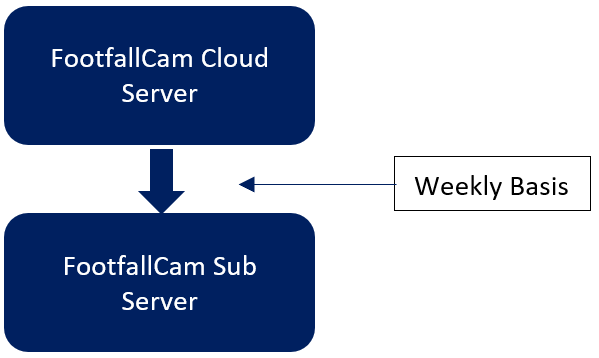
Contingent Full Backup |
FootfallCam Sub Server |
Weekly |
Every week G.M.T +0 3:00 A.M |
12.1.4 Backup Content
12.1.4.1 System
System file shall be backup in the latest version.
12.1.4.2 Data
|
Backup |
Type of Data |
Size |
|
Full Backup |
All Data including customer data, footfall data, Wi-Fi data and Counter Configuration Data |
Varied with the number of counters |
|
Redundant Backup |
Counter Configuration Data including: a. Server Details b. Company Settings c. Site / IT Details d. User Access & Details e. Counter & Camera Settings f. Verification Status |
Varied with the number of counters |
|
Contingent Full Backup |
Counter Configuration Data including: a. Server Details b. Company Settings c. Site / IT Details d. User Access & Details e. Counter & Camera Settings f. Verification Status |
Varied with the number of counters |
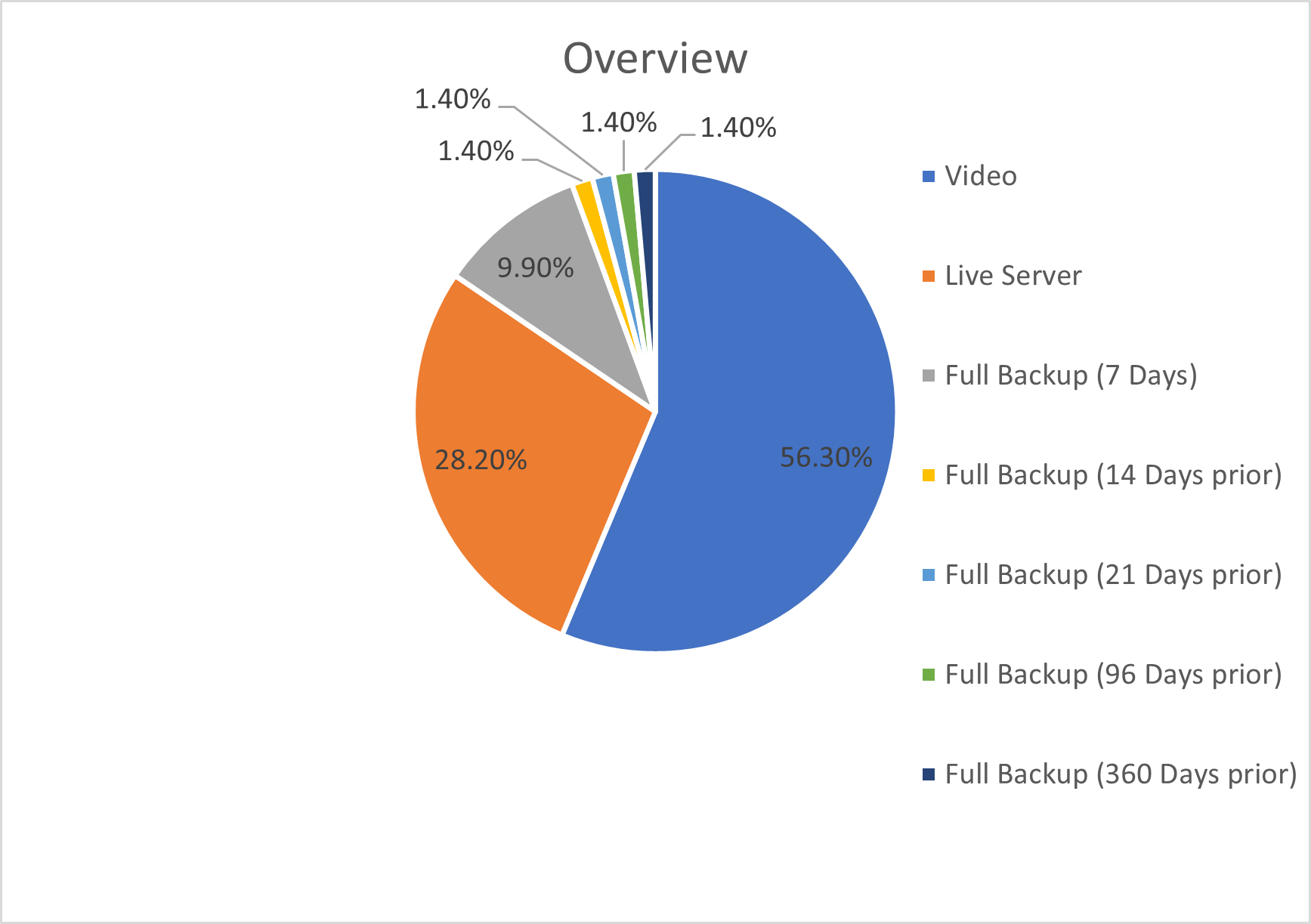
12.1.4.3 Size & Storage
Total server storage suggested is 500GB with RAID.
Overview (per 2000 counters)
|
Component |
Size per Counter / Backup |
Frequency |
Total Size |
Percentage |
|
Video (Verification) |
100MB |
2000 |
200GB |
56.3% |
|
Live Server |
-- |
-- |
100GB |
28.2% |
|
Full Backup |
5GB |
7 Days |
35GB |
9.9% |
|
14 Days prior |
5GB |
1.4% |
||
|
21 Days prior |
5GB |
1.4% |
||
|
96 Days prior |
5GB |
1.4% |
||
|
360 Days prior |
5GB |
1.4% |
||
|
Total |
-- |
-- |
355GB |
100% |
Server Level Data (per counter)
|
Type of Data |
Data Size |
|
|
Raw Data |
Counting Data |
Varied with the number of counters |
|
MAC Address Wi-Fi Data |
Varied with the number of counters |
|
|
Aggregated Data |
Counting Data + Wi-Fi Data |
Varied with the number of counters |
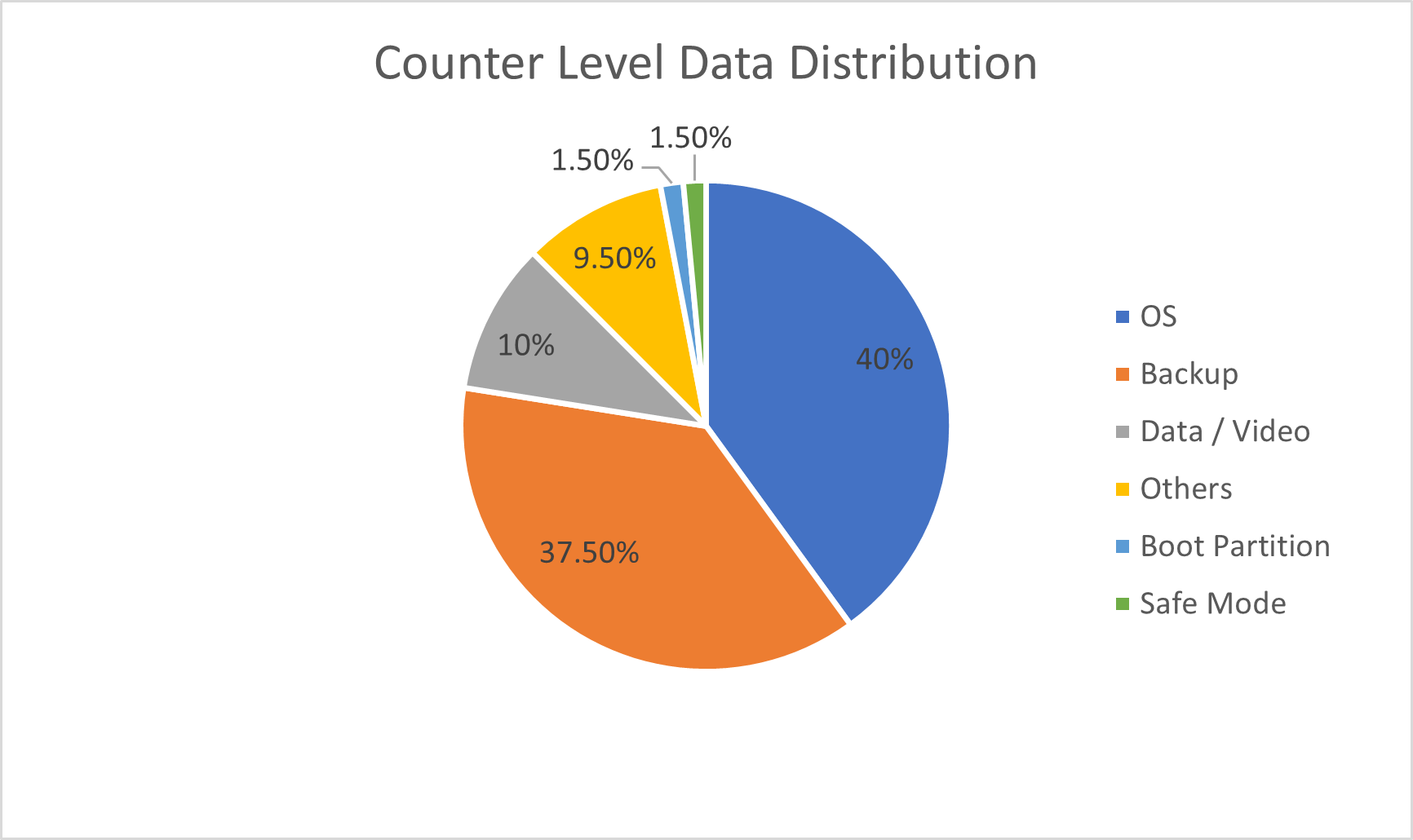
Counter Level Data (per counter)
Each counter comes with 4GB storage
|
Component |
Size |
Percentage |
|
OS |
1600MB |
40.0% |
|
Backup |
1500MB |
37.5% |
|
Data / Video |
400MB |
10.0% |
|
Others |
380MB |
9.5% |
|
Boot Partition |
60MB |
1.5% |
|
Safe Mode |
60MB |
1.5% |
|
Total |
4000MB |
100% |
12.1.4.4 Backup Type
|
Type of Backup |
Files to be included |
|
Full Backup |
Source files, excluding archive bit |
|
Incremental Backup |
Files that have been changed since last Full Backup, including archive bit |
12.1.4.5 Backup Retention
Server and Counter level data housekeeping starts at G.M.T +0 4:00AM daily.
Server Level Data
|
Type of Data |
Retention Period |
Housekeeping Rule |
|
|
Raw Data |
MAC Address |
30 Days |
For MAC Address > 30 days |
|
Aggregated Wi-Fi |
Lifetime |
-- |
|
|
Video Data |
Normal Video |
7 Days |
For video is unverified > 7 days |
|
Pending Video |
7 Days |
For failed video upload to server |
|
|
Broken Video |
7 Days |
For video duration < 5 minutes |
|
|
Health Check Data |
Counter Heartbeat |
30 Days |
For counter heartbeat > 30 days |
Counter Level Data
|
Type of Data |
Retention Period |
Housekeeping Rule |
|
|
Raw Data |
Counting Data |
7 Days |
For successful data upload to server |
|
180 Days |
For unsuccessful data upload to server |
||
|
MAC Address Wi-Fi Data (Semi Aggregated) |
7 Days |
For successful data upload to server |
|
|
14 Days |
For unsuccessful data upload to server |
||
|
Video Data |
Normal Video |
-- |
For successful video upload to server |
|
3 Days |
For unsuccessful video upload to server. All videos will be cleared if unsuccessful attempts for more than 3 days |
||
|
Health Check Data |
Counter Heartbeat |
30 Days |
For counter heartbeat > 30 days |
12.1.4.6 Backup Failure
In the event of an unsuccessful backup, Client will receive email notification and shall take the following immediate actions:
- Investigate the backup on the client, checking backup logs and resolve the issue
- Resume backup and monitor the backup progress to be performed as usual
- To perform manual backup if the backup fails repeatedly
- Send email request to [email protected] if issue persists
12.1.4.7 Disposal of Damaged Hardware/Software
In the event that the hard disks or other relevant files/data is damaged or corrupted and can no longer be used, authorization for destruction must be obtained from Client's IT Technical Team Leader providing valid reasons.
The disposals must be logged for future reference. All disposals must be disposed safely and securely to prevent third parties from extracting data for unauthorized use.
12.2 Restore
12.2.1 Restore Type
The option to restore data from which server (Client Server, FootfallCam Cloud Server, FootfalCam Sub Server) depends on whether the Client uses own Client Server or FootfallCam Cloud Server.
|
Situations where: |
Restore with: |
|
|
1. |
HDD Failure |
Full Back up from Client Server / FootfallCam Cloud Server |
|
2. |
Server Accessible |
Full Back up from FootfallCam Cloud Server |
|
3. |
Server Failure / Not Accessible |
Full Back up from FootfallCam Cloud Server |
|
4. |
Server Migration |
Full Back up from FootfallCam Cloud Server |
|
5. |
Total Server Destruction |
Full Back up from FootfallCam Sub Server Redundant Backup from FootfallCam Cloud Server |
12.2.2 Restore Procedure and Implementation
Full Restoration:
- Full configurations will be restored from the backup server and controlled through Client server control panel.
- In the case of corrupted data download, loaded data will be automatically deleted. Re-download will be prompted.
Partial Restoration is not available by any means.
12.2.3 Restore Checking
FootfallCam will perform checking on the restored settings to ensure all restorations are performed as scheduled.
12.2.4 Recovery Log
All recovery logs are created electronically by the recovery software
12.2.5 SLA for Data Recovery/ Restore
- Request for Data Restoration - Data restore request by Client may be initiated through email to [email protected] as an extended service request
- Recovery Points - Available recovery point is subject to the availability of backup data scheduled on specific date. By default, all
- Response Time to Recovery Requests - Four (4) working hours are required for FootfallCam to diagnose the recovery requirement and subsequent hours are required to fully restore the system depending on the size of data to be restored.
- Client Responsibilities - Client is required to raise any issue pertaining to data backup and restore. It is the Client's responsibility to make a copy of full backup from Client Server for own protection concern in the event of server failure or server destruction.
- Termination of service - FootfallCam shall not be liable for any form of Client data after termination of service.
- Data is no longer recoverable - In the event of server failure or server destruction, data pertaining to customers, Wi-Fi and Footfall will not be recoverable unless a copy of Full Backup is available from Client (refer to clause v.d. Client Responsibilities)
12.2.6 Backup and Restore Process Failures
In the event of the following occurrences, alarms via email notifications will be sent to Client support email daily.
- HDD Failure
- Full HDD storage (<15% memory available)
- Server Control Panel Software Failure
12.2.7 Contingency Plan
In the event of serious data destruction (e.g. server destruction), one copy of Full Backup will be available from FootfallCam Sub server for recovery purpose. This Full Backup is scheduled weekly to FootfallCam Sub Server.
Only three (3) copies of latest Full Backup (7 days, 14 days and 28 days before current date) will be kept.
Chapter 13: API Documentation- Data Export and Import
13.0 Overview
Conventional FTP Data Retrieval
| Method | FTP |
| Minutely/ Hourly | Raw Data/ Per Minute Data |
| Number of File Sent |
Based on number of counters installed, one file per counter on daily basis |
|
Data Retrieving Time |
2.30am according to Clients' time zone |
Disadvantages of using conventional method:
- Relatively hard to maintain
- No visibility on FTP success rate to to Client server
- Raw data are not aggregated. Self aggregation and comparison are required. Raw files not combined to branch levels if one of the counters is offline, it would result in lower branch level traffic
- No visibility on whether late data will be re included next day
- Data Integrity: Inaccurate data especially when one offline counter affects the overall accuracy of counting, in terms of sales conversion, visitor counts etc. No visibility if data retrieved is partially completed or fully completed, if it is clean data with no offline
counters and no unverified data
Proposed Solution:
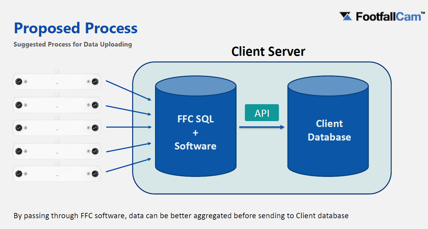
- Ensure the data collected is fully verified
- Ensure the branch level data collected has no missing data due to one of the counter offline
- Ensure the data is fully uploaded to the server and get the complete set to compare with sales
conversion
13.1 Integration with Incumbent People Counter
User may choose to migrate historical data from incumbent device into FootfallCam Analytic Manager The process will take up to a week to generate reports based on the historical data.
However, this function is currently not available for public release. If you would like to migrate your data from your existing people counter, please email to FootfallCam Sales Team.
13.2 Data Retrieve
FootfallCam is a fully embedded software module, intended for any environment where store footfall counting is required. Business intelligence (BI) system extracts and analyses footfall data (from FootfallCam central server) together with ePOS data or staff labour hours (from retailer's ePOS system or staff management system) to produce management report for corporate strategic planning. By default, user able to obtain footfall data directly from counter or server via several types of methods which are listed as below:
13.2.1.1 Retrieve Data via API from device
STEP 1 - Generate URL: http://[insert Internal IP]/cgi-bin/access_token.cgi?username=[insert Username] &password=[insert Password]
| Item | Description |
| Internal IP | Retrieve the Internal IP.
(Info: For more information on Internal IP, please refer to Section 6.2.) |
| Username | admin
(Info: Case sensitive.) |
| Password | (Info: Same password used to login to Counter Setup Wizard, therefore it is counter-dependent. NOT the password used to login to counter Wi-Fi) |
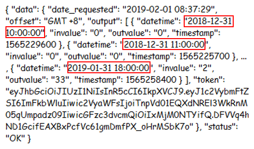
STEP 2 - Run the URL and access token received will be shown as below.
| URL | Output |
| http://192.168.2.123/cgi-bin/access_token.cgi?username=Admin&password=[password] | 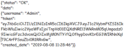 |
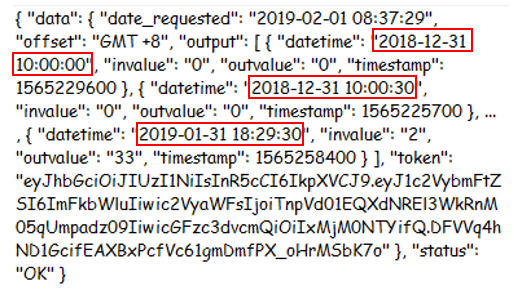
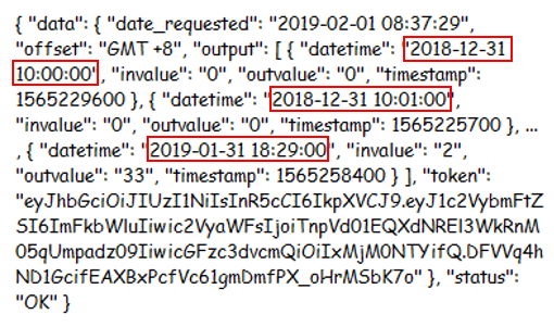
STEP 3 - Retrieve data using access token received. Generate URL with the selected parameter listed as below: http://[insert Internal IP]/cgi-bin/apiCount_cgi?data_type=[insert Data Type]&data_format=[insert Data Format]&resolution_min=[insert Resolution Minutes]&date_start=[insert Date Start]&date_end=[insert Date End]&time_start=[insert Time Start]&time_end= [insert Time End]&access_token=[insert Token]
| Parameter | Description | Value | Sample |
| Data Type | Type of the data. | json, xml | data_type=xml |
| Data Format | Format of the data. | hour, minute, second | data_format=second |
| Resolution Minutes | The minutes data's resolution. | 1, 5, 10, 15, 30, 60 | resolution_min=15 |
| Resolution Second | The second data's resolution. | 1, 5, 10, 15, 30, 60 | resolution_sec=1 |
| Date Start | Start date of the data. | YYYYMMDD | date_start=20181231 |
| Date End | End date of the data. | YYYYMMDD | date_end=20190131 |
| Time Start | To set the start time range of the API | HHmmss | time_start=103000 |
| Time End | To set the end time range of the API | HHmmss | time_end=223300 |
13.2.2 Retrieve Live Data via WebSocket
13.2.2.1 WebSocket Client
With this module, counting data is able to be sent to your websocket server as it happens. Please consult your IT Technician if it is possible to set up a websocket server to receive our live counting data.
For this to be set up, there are several requirements:
7.3.2.2 Setting up the Websocket Module
|
Requirement |
|
|
Websocket Server Address |
Data MUST be acknowledged with OK upon receiving them, otherwise, FootfallCam counter will assume the sending has failed and keep re-sending the same data. |
|
Basic Authentication (Optional) |
Username and Password |
In your Counter's Control Panel, navigate to the Settings tab and scroll down to find 'Websocket Module'.
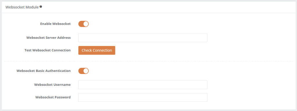
Once enabled, you can fill in your Websocket Address in the field provided. If Basic Authentication is enabled in your Server, you may toggle the option and fill in the details. Otherwise, this option is optional.
Every time the setting is changed, Check Connection must be clicked before saving it to allow the Counter to test the connection.
- The Websocket Server should receive a JSON test data with the topic 'generic-test-topic'.
- The Websocket Server must return "OK".
7.3.2.3 Websocket Module: Data Explanation
|
Parameter |
Description |
Value |
|
Topic |
Name of the payload which IN / OUT data will send to server. |
ffc-eventrawdata |
|
CameraSerial |
Unique ID. (Info: You may obtain the CameraSerial by getting the Chipset Code from Home page.) |
00000000xxxxxxxx |
|
EventStartUTCTime |
Start of Event in UTC Timezone. |
YYYY-MM-DD HH:MM:SS |
|
EventEndUTCTime |
End of Event in UTC Timezone. |
YYYY-MM-DD HH:MM:SS |
|
EventStartTime |
Event Start Time in Linux Timestamp |
YYYY-MM-DD HH:MM:SS |
|
EventEndTime |
Event End Time in Linux Timestamp |
YYYY-MM-DD HH:MM:SS |
|
EventStartLocalTime |
Event Start in Local Time. |
YYYY-MM-DD HH:MM:SS |
|
EventEndLocalTime |
Event End in Local Time. |
YYYY-MM-DD HH:MM:SS |
|
UploadedUTCDateTime |
UTC Time of when the Data is published to be sent. |
YYYY-MM-DD HH:MM:SS |
|
UploadedLocalDateTime |
Local Time of when the Data is published to be sent. |
YYYY-MM-DD HH:MM:SS |
|
MetricId |
To indicates kind of event triggered such as Value IN or Value Out. |
1 = ValueIN 2 = ValueOut |
|
PeopleTypeId |
To indicate which kind of people were detected. |
1 = Visitor 2 = Staff |
|
Roild |
Temporarily ONLY for Internal Use. |
N / A |
|
PeopleId |
To indicate the people are being tracked. Example, multiple people will be indicate with different IDs. |
numeric |
| Sample 1 - Value IN Data |
| {'Topic': 'ffc-eventrawdata', 'Data': {'EventStartUTCTime': '2020-06-17 03:16:41', 'EventEndLocalTime': '2020-06-17 11:16:41', 'EventStartTime': 1592363801, 'MetricId': 1, 'RoiId': 1, 'CameraSerial': '000000006afce315', 'PeopleId': 1, 'EventEndUTCTime': '2020-06-17 03:16:41', 'UploadedLocalDateTime': '2020-06-17 11:16:45', 'EventEndTime': 1592363801, 'EventStartLocalTime': '2020-06-17 11:16:41', 'UploadedUTCDateTime': '2020-06-17 03:16:45', 'PeopleTypeId': 1}} |
| Sample 2 - Value OUT Data |
| {'Topic': 'ffc-eventrawdata', 'Data': {'EventStartUTCTime': '2020-06-17 03:20:18', 'EventEndLocalTime': '2020-06-17 11:20:18', 'EventStartTime': 1592364018, 'MetricId': 2, 'RoiId': 1, 'CameraSerial': '000000006afce315', 'PeopleId': 1, 'EventEndUTCTime': '2020-06-17 03:20:18', 'UploadedLocalDateTime': '2020-06-17 11:20:21', 'EventEndTime': 1592364018, 'EventStartLocalTime': '2020-06-17 11:20:18', 'UploadedUTCDateTime': '2020-06-17 03:20:21', 'PeopleTypeId': 1}} |
13.2.3 Retrieve Data via Data Integration Tool
13.2.3.1 Download Link (Supports Windows 64-bit devices only)
13.2.3.2 Build/Send Query
STEP 1 - Select the API Type (Authentication/Hourly Data/Minutes Data/Seconds Data/Most Recent 60 Seconds Data).
STEP 2 - Fill in required fields accordingly.
STEP 3 - Click the Copy icon to copy Query, or the Send Query button to send Request.
13.2.3.3 Copy Code Snippets
STEP 1 - Select the API Type (Authentication/Hourly Data/Minutes Data/Seconds Data/Most Recent 60 Seconds Data).
STEP 2 - Fill in required fields accordingly.
STEP 3 - Select Language.
STEP 4 - Click the Copy icon to copy Code Snippet.
13.2.3.4 Link Counter to Local WebSocket Server
STEP 1 - Click the Copy icon to copy Local WebSocket Address.
STEP 2 - Navigate to Counter Setup Wizard of the counter that you wish to test WebSocket connection in your web browser.
STEP 3 - Navigate to IT Settings page, then to WebSocket Module under Advanced IT Settings section.
STEP 4 - Toggle WebSocket to "ON".
STEP 5 - Paste into WebSocket Server Address text input.
STEP 6 - Click Test Connection button.
STEP 7 - Click Save button.
STEP 8 - You should be seeing IN/OUT data (Including test connection) displaying in Response in Data Integration Tool app.
13.2.4 Retrieve Data via FTP
13.2.4.1 FTP directly from counter
| Time of Output | Once per day |
| Minimum Resolution | Once per 1 minute |
| Data Presentation | By Counter level |
- Access the Configuration page on the menu bar on the left
- Scroll to the Direct Export from Counter section in the newly landed page
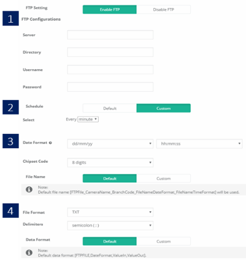
- Click on the option of Enable FTP.
- Fill in the required details:
| Item | Description |
| 1. FTP configurations | FTP account details |
| 2. Schedule | How often should the data be exported |
| 3. Date Format | The date format that will appear on the data |
| 4. File name | Name of the exported file |
| 5. File format | Format of the exported file |
Overall process flow of FTP directly from counter
13.2.4.2 FTP push from Server
| Time of Output | Daily of Weekly |
| Minimum Resolution | 1 hour |
| Data Presentation | By Branch level |
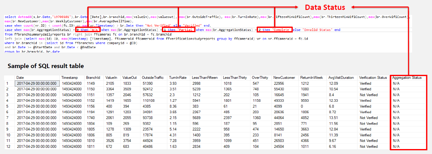
| Types of Data | IN and OUT values, Outside Traffic, Turn In Rate, Verification and Aggregation Status |
| Output format | .xlsx or .csv format |
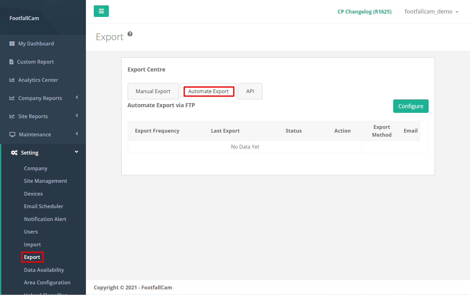
- Select Export Centre on the menu bar on the left
- Click on the tab Automate Export
- Click on Configure to create a new FTP schedule
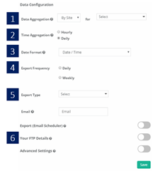
- Fill in the details as required
|
Item |
Description |
|
1. Data aggregation |
Level of data to export and which site should be exported |
|
2. Time aggregation |
Time frame of the data to be exported |
|
3. Date format |
Format of data that will be shown in the export file |
|
4. Export frequency |
Frequency of the export schedule |
|
5. Export type |
Select the file format to be exported |
|
6. FTP details |
Input your FTP account details |
13.2.5 Retrieve Data via SQL
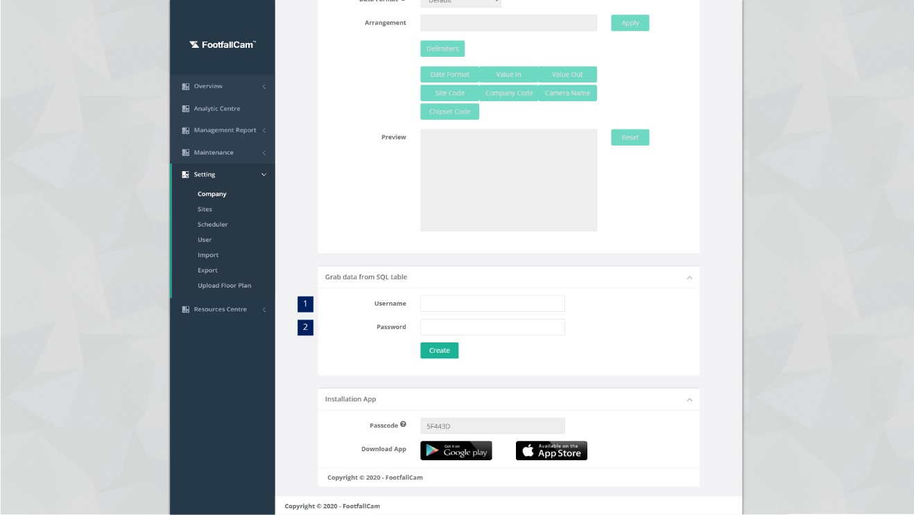
STEP 1 - Click on Setting > Company to access the Control Panel Setting page.
STEP 2 - Navigate to section Grab Data from SQL Table.
STEP 3 - Complete the process by entering all the required fields and click on Create button.
| Item | Description |
| 1. Username | Username used to access FootfallCam Analytic Manager V9™. |
| 2. Password | Password used to access FootfallCam Database Server. |
Example updated on 2021-02-25:
| Analytic Manager UserName | Analytic Manager Password | SQL Server UserName | SQL Server Password |
| abc | 123 | xyz | 789 |
| Old approach : Select * from functionName ('abc', '123'); Exec functionName ('abc', '123'); |
|||
| New approach : Select * from functionName ('abc', '789'); Exec functionName ('abc', '789'); |
|||
Note: Password '789' is only example password. For security concern, it's encourage user to set a complicated pattern set.
| Sample 2 - How to get Counter List | |
| Description | To retrieve counter list and site info include ID, CameraName, IP, Port, Serial. |
| Function Name | GetCounterByBranch |
| Data Params | Username [nvarchar]; Password [nvarchar]; Branchid[bigint] |
| Sample SQL | SELECT * FROM GetCounterByBranch('username', 'password', 37); |
| Sample Result |  |
| Sample 1 - How to get Site List | |
| Description | To retrieve site list and site info include BranchCode, BranchName, Region, City, Country, StoreType, Latitude, Longitude and Floorsize. |
| Function Name | GetBranchList |
| Data Params | Username [nvarchar]; Password [nvarchar] |
| Sample SQL | SELECT * FROM GetBranchList('username','password'); |
| Sample Result | 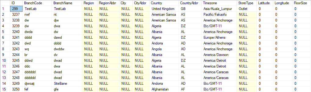 |
| Sample 3 - How to get Hourly Counting data by Site | |
| Description | To retrieve site hourly counting data include Branchid, ValueIn, ValueOut, OutsideTraffic, TurnInRate. |
| Function Name | GetBranchHourly |
| Data Params | Username [nvarchar]; Password [nvarchar]; BranchCode [bigint]; StartDate [datetime]; EndDate [datetime] |
| Sample SQL | SELECT * FROM GetBranchHourly('username', 'password', -1, '20150320', '20150321'); |
| Note | -1 refer to the company which means all site(s). |
| Sample Result | 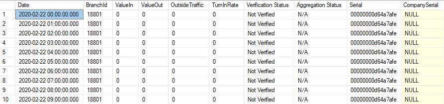 |
| Sample 4 - How to get Daily Counting data by Site | |
| Description | To retrieve site daily counting data include Branchid, ValueIn, ValueOut, OutsideTraffic, TurnInRate. |
| Function Name | GetBranchHourly |
| Data Params | Username [nvarchar]; Password [nvarchar]; BranchCode [bigint]; StartDate [datetime]; EndDate [datetime] |
| Sample SQL | SELECT * FROM GetBranchDailySummary('username', 'password', 410, '20140120', '20140121'); |
| Note | -1 refer to the company which means all site(s). |
| Sample Result | 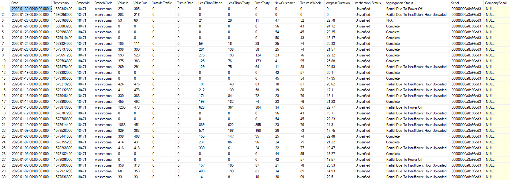 |
| Sample 5 - How to get Area List | |
| Description | To retrieve area list and area info include BranchId, BranchName, AreaId, AreaName, CameraId, CounterName, CompanySerial, CounterChipsetCode, LineName and Direction |
| Function Name | GetAreaConfiguration |
| Data Params | Username [nvarchar]; Password[ nvarchar]; BranchID [nvarchar] |
| Sample SQL | select * from GetAreaConfiguration('Username', 'Password', -1) |
| Note | -1 which means all site(s) in the company. |
| Sample Result | 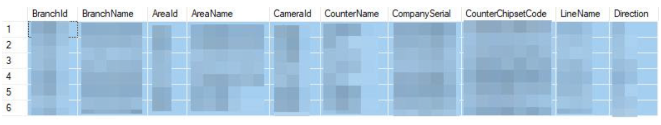 |
| Sample 6 - How to get Hourly Counting data by Area | |
| Description | To retrieve area hourly counting data include AreaId, AreaName, ValueDateTime, ValueIn, ValueOut |
| Function Name | GetAreaHourly |
| Data Params | UserName [nvarchar]; Password [nvarchar]; AreaID [nvarchar]; StartDate [datetime]; EndDate [datetime] |
| Sample SQL | select * from GetAreaHourly('Username', 'Password', -1, '2021-01-13 00:00:00.000','2021-01-14 00:00:00.000') |
| Note | -1 which means all area(s) in the company. |
| Sample Result | 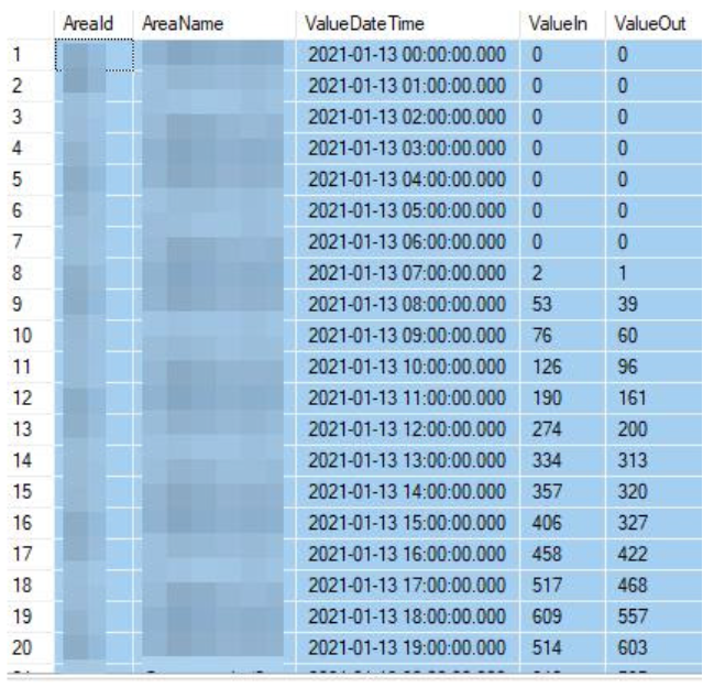 |
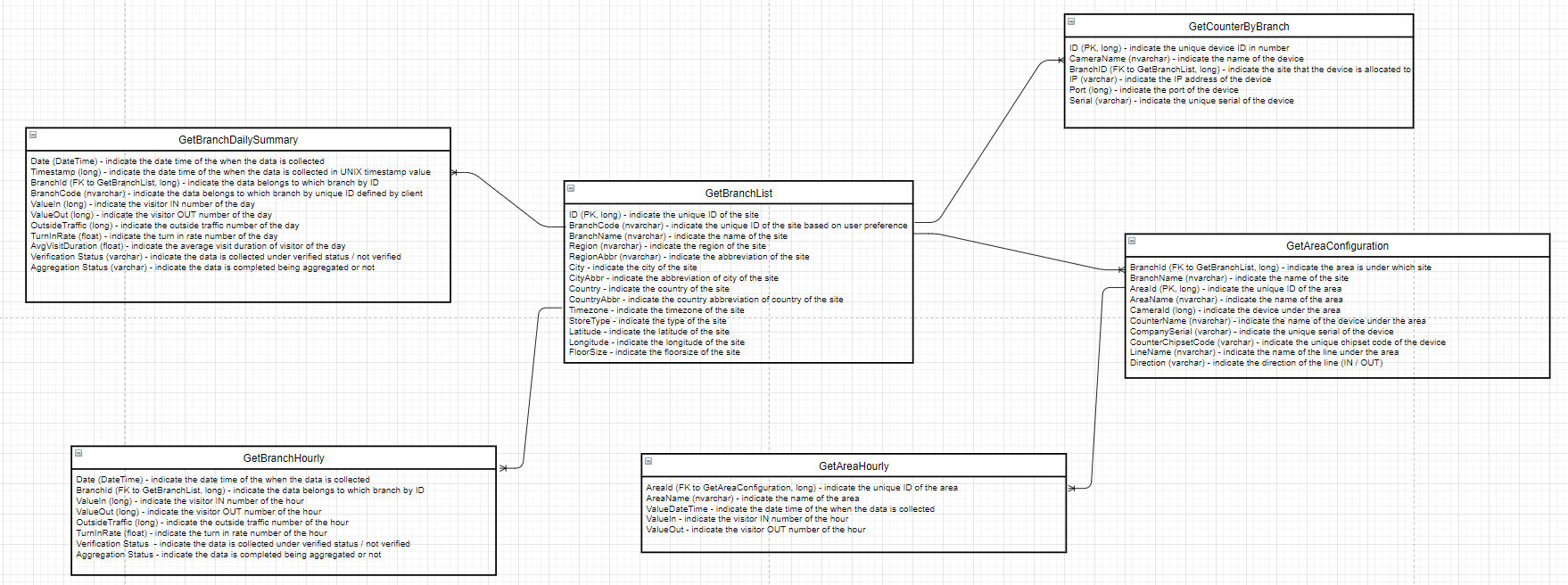
13.2.5.1 Schema
13.2.6 Retrieve Data by Manual Export Function
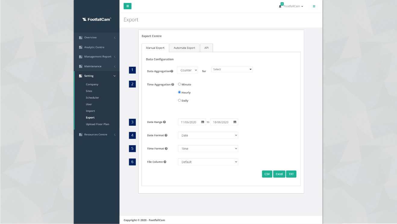
STEP 1 - Click on Setting > Export to access the Export page.
STEP 2 - Click on Manual Export tab to access the Manual Export tab.
STEP 3 - Complete the process by entering all the required fields and click on CSV / Excel / TXT button.
| Item | Description |
| 1. Data Aggregation | Select the site / counter. |
| 2. Time Aggregation | Select the length of data. |
| 3. Date Range | Select the start date and end date. |
| 4. Date Format | Select the format of the date. |
| 5. Time Format | Select the format of the time. |
| 6. File Column | Arrangement of column in download file. (Info: User able to re-organize the data column if user selected custom mode.) |
13.2.7 Retrieve Data by Auto Scheduled on Web Portal
Data can be schedule to auto generate and export to your email according to the frequency set. Below are the steps to configure the automated export setting.
STEP 1 - Click on Setting > Export to access the Export page.
STEP 2 - Click on Automate Export tab to access the Manual Export tab.
STEP 3 - Click on Configure button to access Configure Automate Export Setting page.
STEP 4 - Complete the process by entering all the required fields and click on Save button.
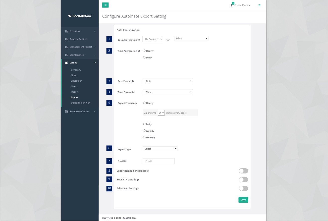
| Item | Description |
| 1. Data Aggregation | Select the site / counter. |
| 2. Time Aggregation | Select the length of data. |
| 3. Date Format | Select the format of the date. |
| 4. Time Format | Select the format of the time. |
| 5. Export Frequency | Select the export frequency. |
| 6. Export Type | Select the export format type. (Info: There are 3 export type: Excel , CSV , TXT) |
| 7. Email | Email address (Info: Notification will be sent to this email if the automated export is failed.) |
| 8. Export (Email scheduler) | Active schedule for export data email. |
| 9. Your FTP Details | FTP details to receive exported file. |
| 10. Advance Setting | Advance setting that included Encryption Mode and Connection Ty[e. |
19.2 Queue Management Report
The queue management report template is located in the Standard Template Folder entitled "[Template] Queue Management Report". To subscribe the queue counting feature, the counter is required to tick "Queue Management" as counter usage. You may refer to this link on how to set counter usage.
19.2.1 Report Creation
There are 2 methods to create this report.
Method 1
Create report by clicking "+ New Dashboard / Report"
Step 1: Configure the field on the report creation modal. You may refer to the image below for the configuration.
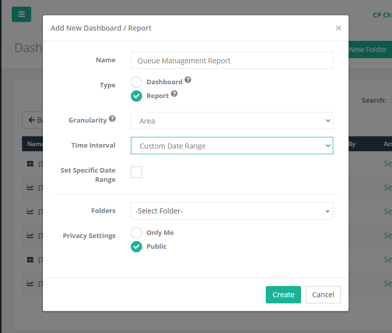
Name:
Users are required to enter a name for the report. (Maximum 40 characters)
Type:
Select Report.
Granularity:
Select Area to monitor each individual queue area.
Time Interval:
For Report, the dropdown option will exclude the "Live" option. If "Custom Date Range" is selected, Set Specific Date Range checkbox will be shown. If the checkbox is selected, users are required to choose Start Date and End Date for the report, else if the checkbox is unselected, the Start Date and End Date will be reset to null. If "Based on Marketing Campaign" is selected, the granularity will be reset to "Site" and set as readonly.
Folders:
Users are required to select the report's location. If no folder is selected, the location of the report will be on the main page. If a folder is selected from the dropdown list, the new report will be located at the selected folder.
Privacy Settings:
If a folder is selected, the privacy settings will be overwritten with the selected folder's privacy settings and set the field as readonly, else if no folder is selected, users are able to select the privacy settings of the new report.
If the role of the login user is User (not Admin), the user is not allowed to create a new report and the report creation button is hidden.
Method 2
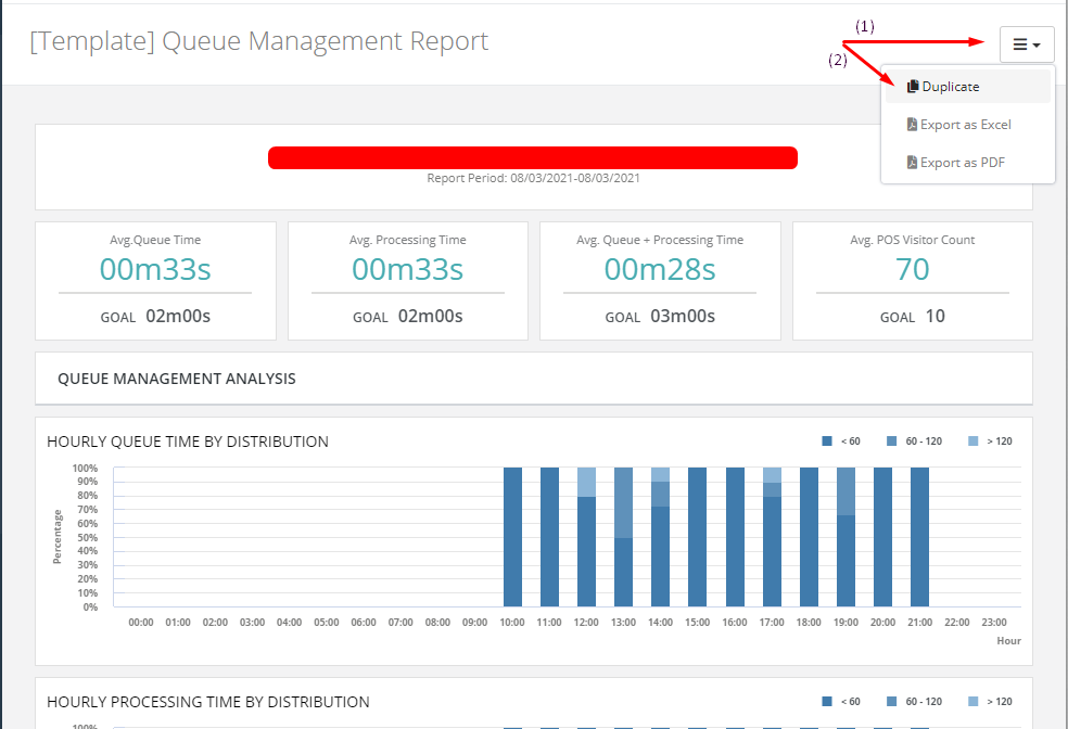
Duplicate the report in Standard Template Report folder
Step 1: Click the "View" button to access the Standard Template Folder.
Step 2: Click the "View" button to view the [Template] Queue Management Report. Click the Option button on the top right as shown in the image below. Then, click "Duplicate".
19.2.2 Area Configuration for Queue Management
To monitor each individual queueing area for each counter, you may configure each individual counter as an Area.
For more information on Area Configuration, please refer to Chapter 21.2 Area Configuration.
Chapter 20: Zone Counting Configuration
20.1 Zone Counting for Malls
20.1.1 Zone configuration
For zone configuration to be done, it require floorplan of the mall to be uploaded. If there is no floorplan for the zone that is about to be configured, please follow 16.3.1 https://www.footfallcam.com/people-counting/knowledge-base/chapter-16-heat-map-configuration/
20.1.1.1 Identifying the zone
After the floor plan has been uploaded into the FootfallCam Analytic Manager, the user will be able to identify the zones within the shopping mall according to the FootfallCam counters that were installed.
STEP 1 - Access to FootfallCam Analytic Manager V9™: http://v9.footfallcam.com via Google Chrome.
STEP 2 - Click on Setting > Zone Configuration to access the Zone Configuration Page.
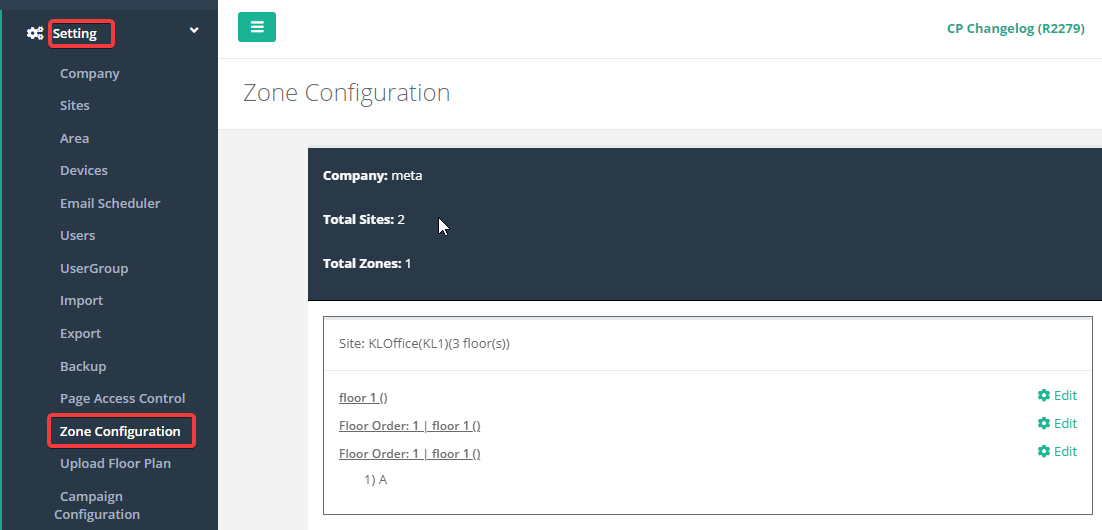
STEP 3 - Click on Edit for the floorplan that wants to add the zone configuration into
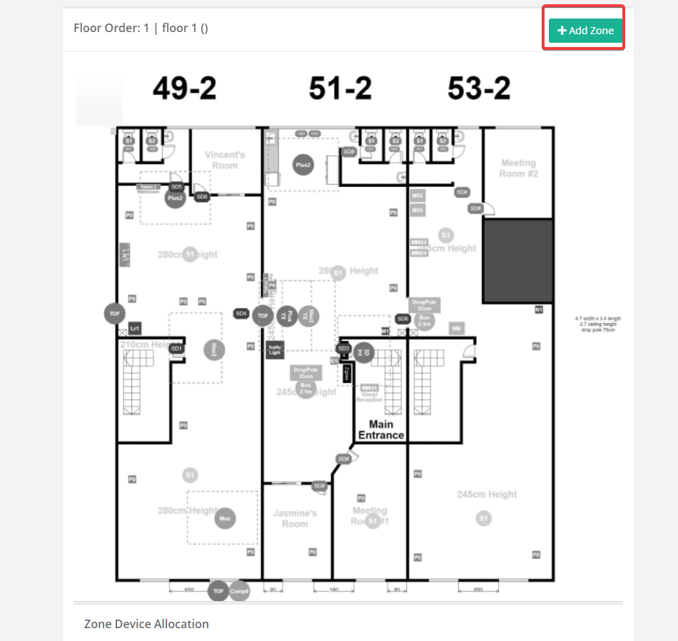
STEP 4 - Click on + Add Zone to add zone into the floorplan
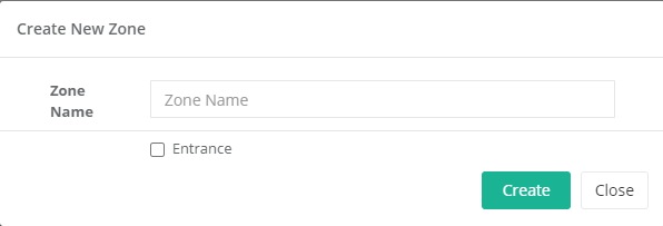
STEP 5 - Enter zone name and if the zone is an entrance to the site, tick the entrance checkbox. Then click on Create
STEP 6 - Drag and drop the newly created zone to where the zone should be on the floorplan.
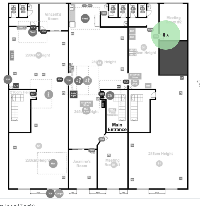
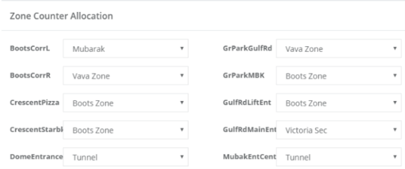
STEP 7 - Select the zone from the drop-down list for each of the counters at the bottom of the page. Once completed click on Save
Note: Only one counter can be allocated to one zone
Chapter 21: Area Counting Configuration
Area counting analysis is one of the traffic analysis method that is normally used in shopping mall, to understand the distribution of visitors throughout the mall and the utilization of the space. Traffic flow analysis provides evidence for management to adjust rental rates of tenants throughout popular areas. Shopper profiling per area also provides showcases where visitors go after visiting a promotional event to offer objective evidence on retail opportunities available on retail tenants.
21.1 Area Counting
A shopping mall can be partitioned into a few area to observe the footfall at that specific area. The area specified required to be configured in FootfallCam Analytic Manager to indicate ROI (Region of Interest) for the footfall counter. (For more information, please refer to Chapter 7: Accuracy Audit.)
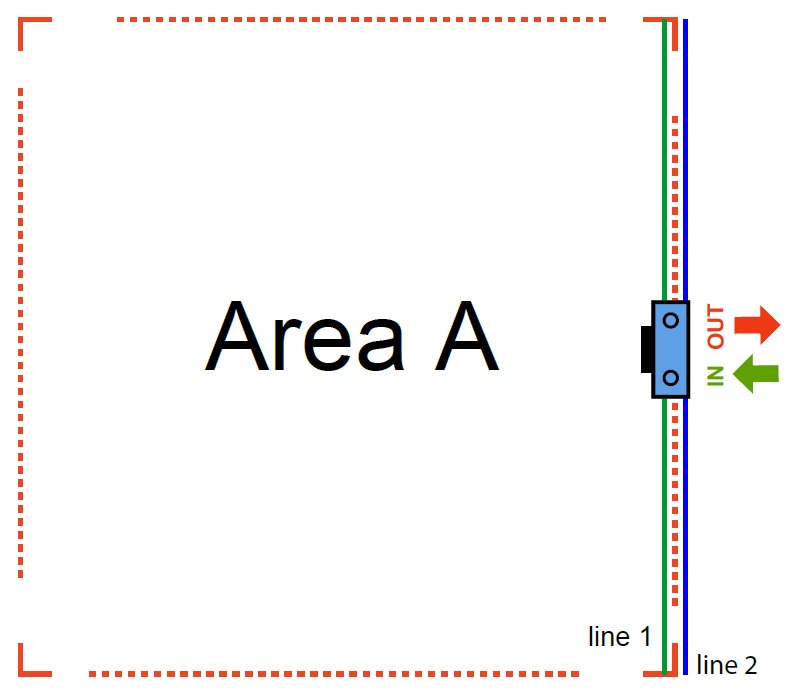
In Area A, line 1 (green line) indicates In line while line 2 (blue line) indicates Out line.
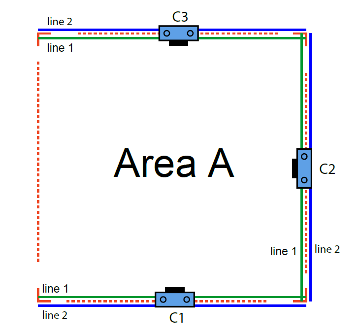
If an area contains more than one counter, then all the counters should be define during area configuration.
The footfall counting data for Area A will be the summation of footfall for counter C1, C2 and C3. Therefore if any of the counters is not define during area configuration, the data will be inaccurate.
The same counter can be used to define two areas or more areas.
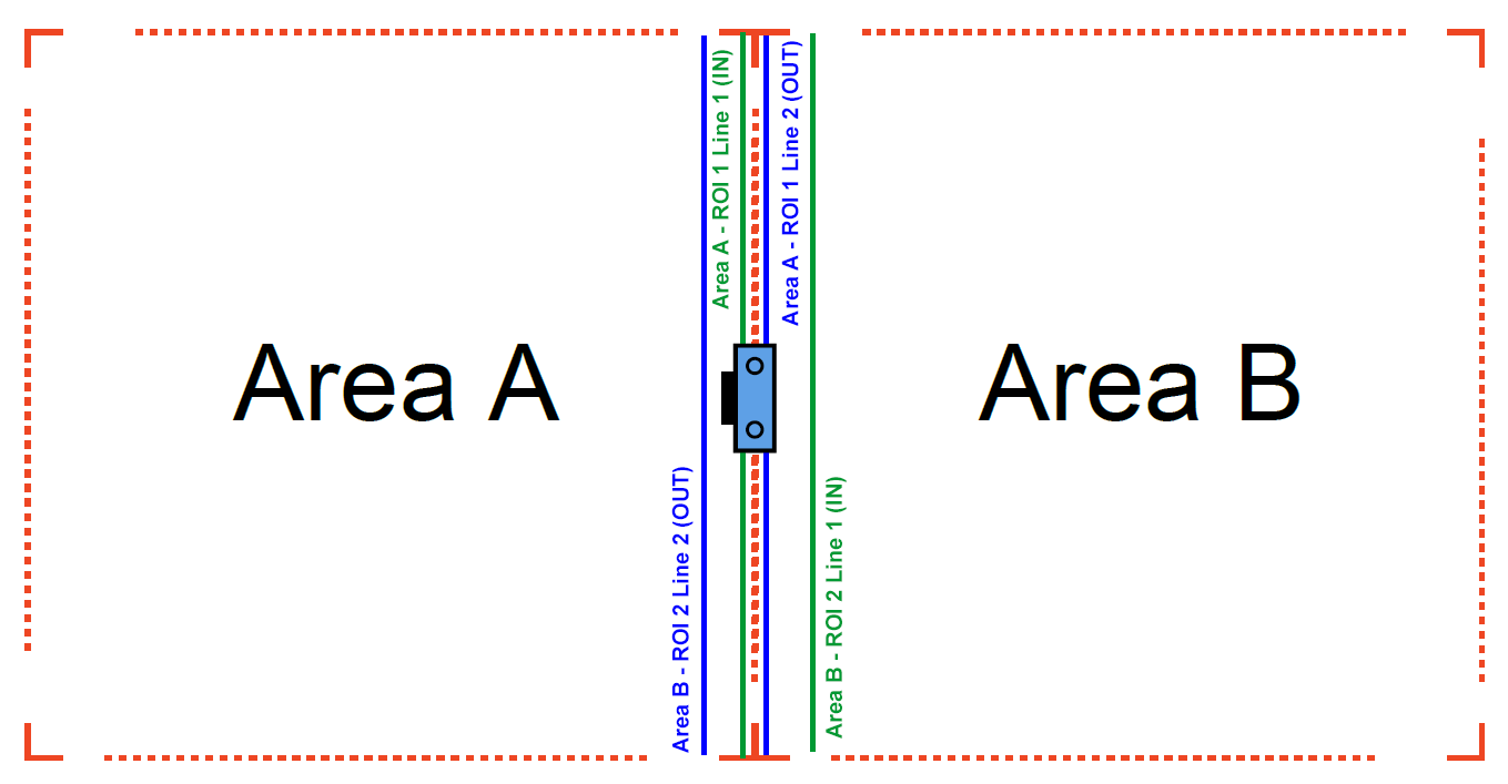
In this situation, the same counter is used for both areas.
For Area A, ROI1 Line1 (green line) indicates In line while ROI1 Line 2 (blue line) indicates Out line.
For Area B,ROI2 Line 1 (green line) indicates In line while ROI2 line 2 (blue line) indicates Out line.
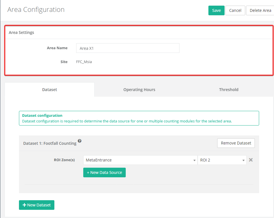
Example of setup:
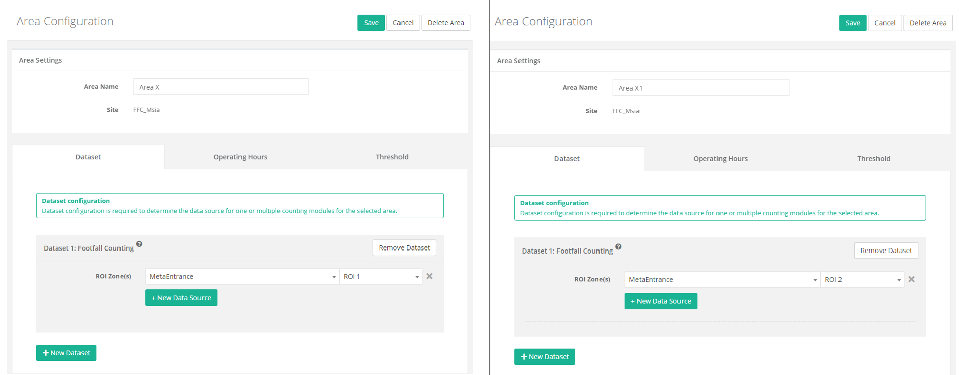
Both AreaX and AreaX1 is in site FFC_Msia, both using the same device which is MetaEntrance. However, one area is using ROI 1 while another one is using ROI2.
This definition will be useful for area configuration in the next section.
21.2 Area Configuration
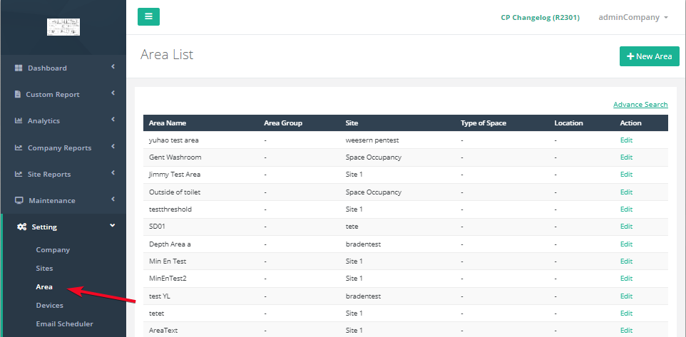
STEP 1 - Access to FootfallCam Analytic Manager V9™: http://v9.footfallcam.com via Google Chrome.
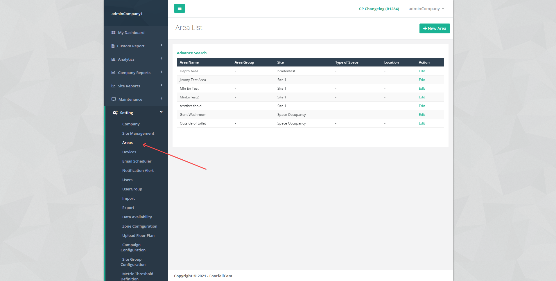
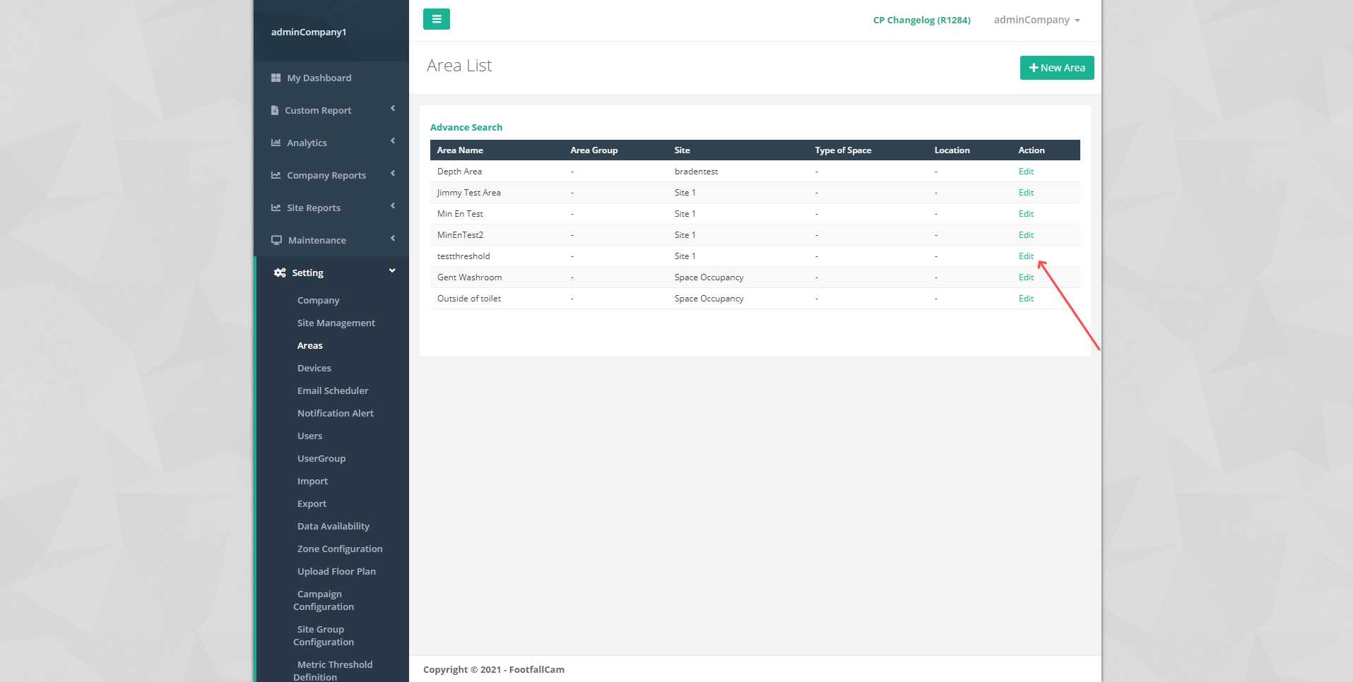
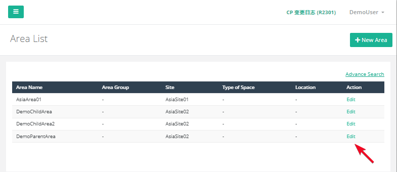
STEP 2 - Click Setting > Area to access the Area List page.
| Item | Description |
| 1. Area Name | Display the area name. |
| 2. Area Group | Display the area group. |
| 3. Site | Display the site of the area. |
| 4. Type of Space | Display the type of space of the area. |
| 5. Location | Display the location of the area. |
| 6. Action | To access the Area Configuration page for the setting. |
21.2.1 Create New Area
STEP 1 - Access to FootfallCam Analytic Manager V9™: http://v9.footfallcam.com via Google Chrome.
STEP 2 - Click Setting > Area to access the Area List page.
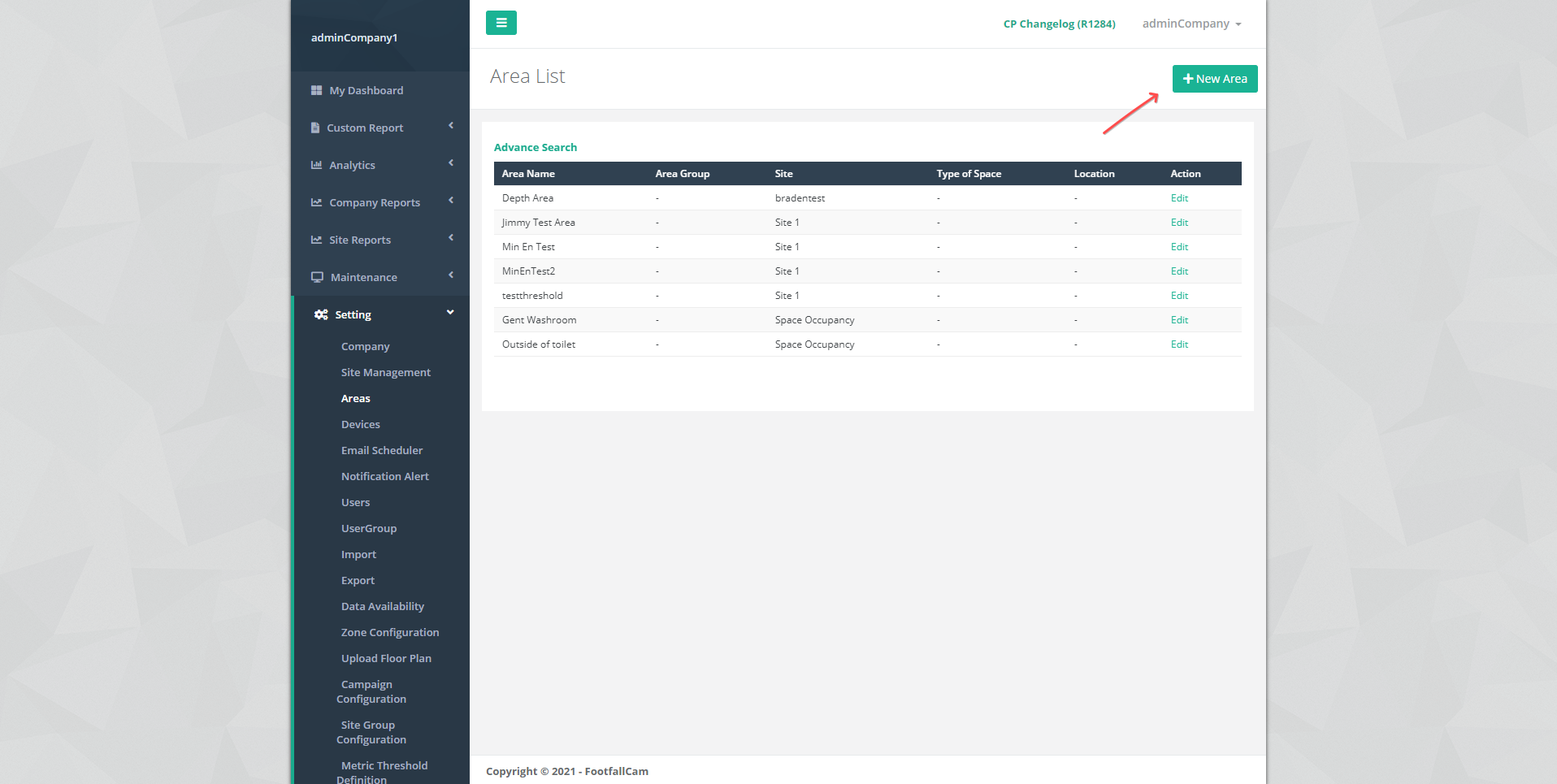
STEP 3 - Click +New Area button to create a new area.
STEP 4 - Fill in relevant information for the required fields.
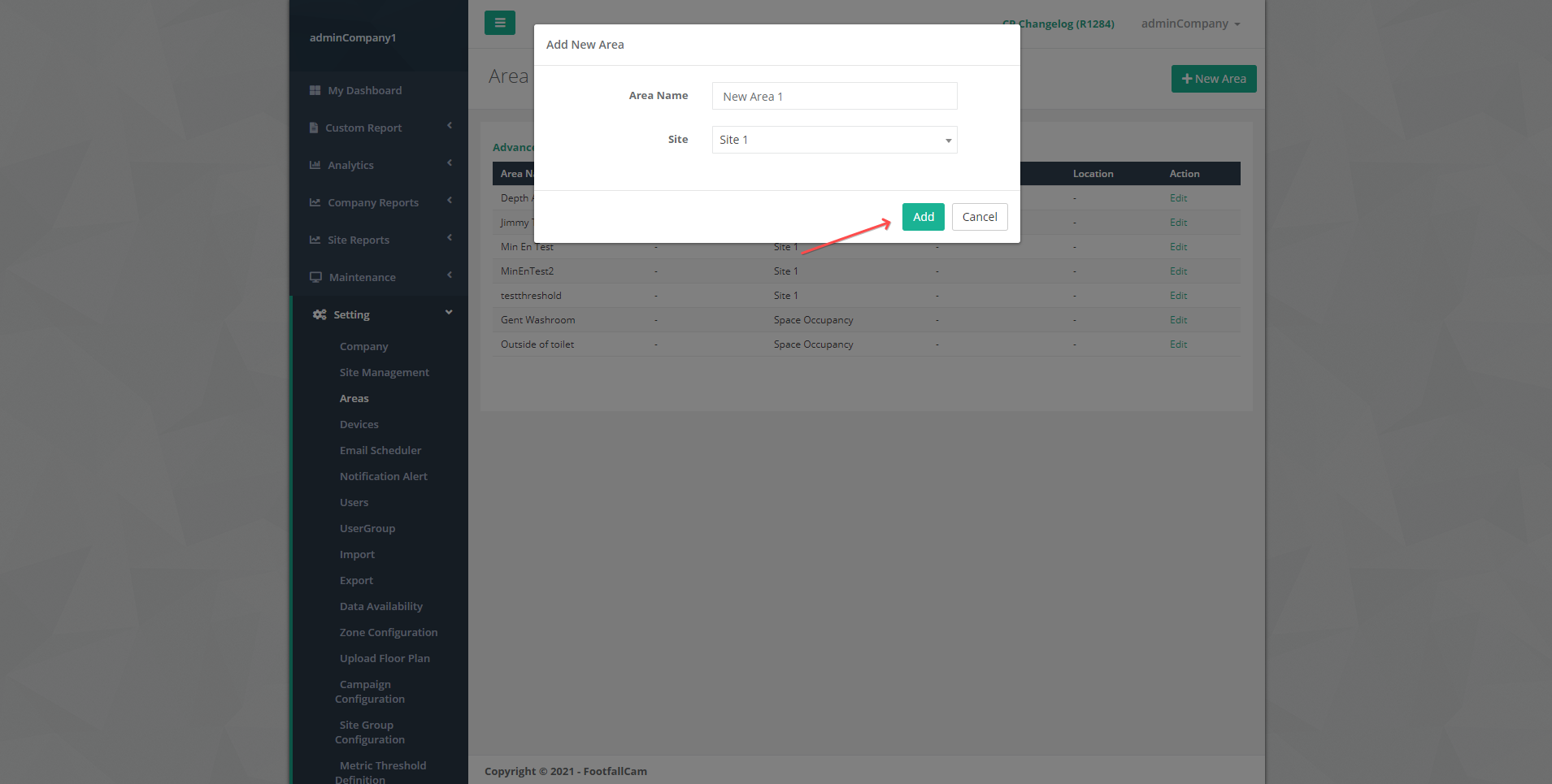
| Field | Description |
| 1. Area Name | Enter your preferred name of the area. |
| 2. Site | Select the Site to add the area. |
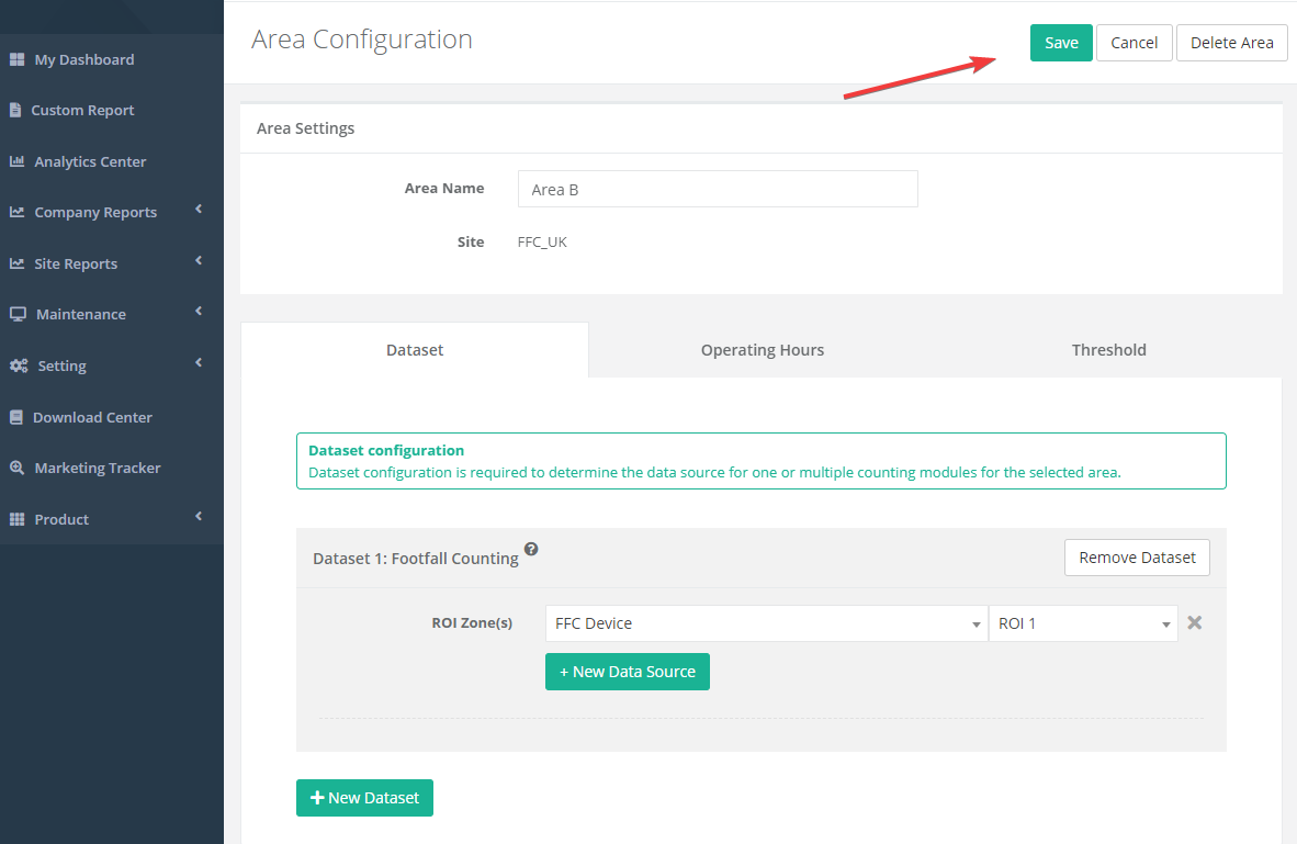
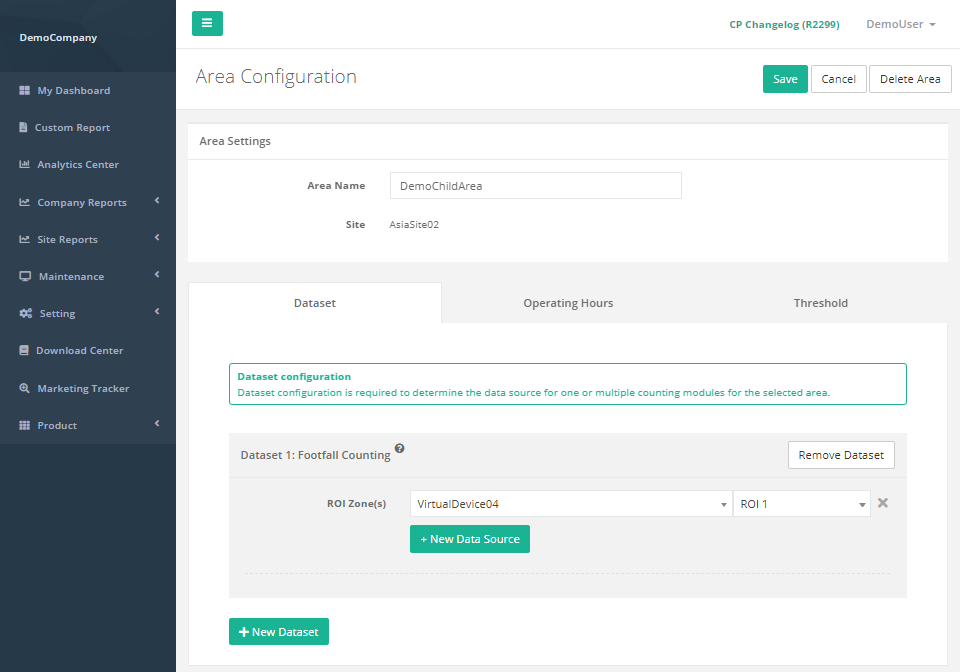
STEP 5 - Click Add button to add the new area. It will be redirect to Area Configuration page.
STEP 6 - Complete the process by entering all the required fields in Dataset tab (Refer to Section 21.2.4 Dataset Configuration for Dataset setting and Section 21.2.5 Threshold Configuration for metric threshold setting).
| Item | Description |
| 1. Area Name | Edit the name of the area that you wish to change. |
| 2. Site | Display the site of the area. |
STEP 7 - Click on Save button to create the area.
21.2.2 Manage Area
STEP 1 - Click Setting > Area to access the Area List page.
STEP 2 - Select the the area you wish to update and click on the Edit button.
STEP 3 - Update the relevant information and click Save to save the changes. Click Cancel if you wish to exit the page.
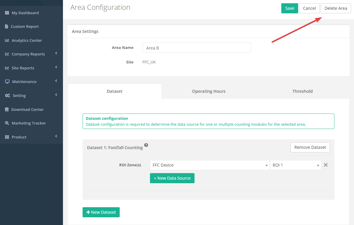
21.2.3 Delete Area
STEP 1 - Click Setting > Area to access the Area List page.
STEP 2 - Select the area that you wish to edit and click on the Edit button.
STEP 3 - Click Delete to delete the area. The deleted area will no longer be reflected in the table located at the Area List page.
21.2.4 Dataset Configuration
STEP 1 - Click + New Dataset to trigger the Add Dataset pop up.
STEP 2 - Select the Counting Module and click Save button to add the dataset.
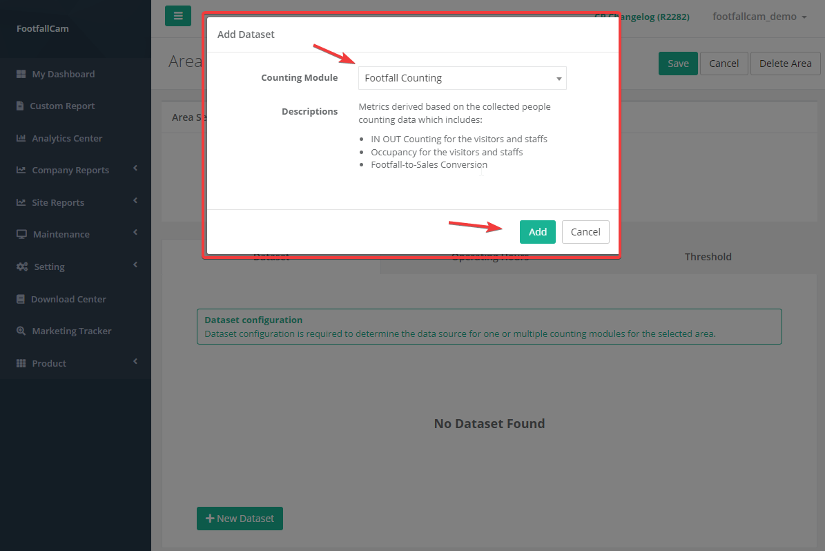
| Item | Description |
| 1. Counting Module |
Select the counting module type that you wish to add.
|
| 2. Add Button | Add new dataset section. |
| 3. Cancel Button | Close the add dataset dialog box. |
21.2.4.1 Footfall Counting
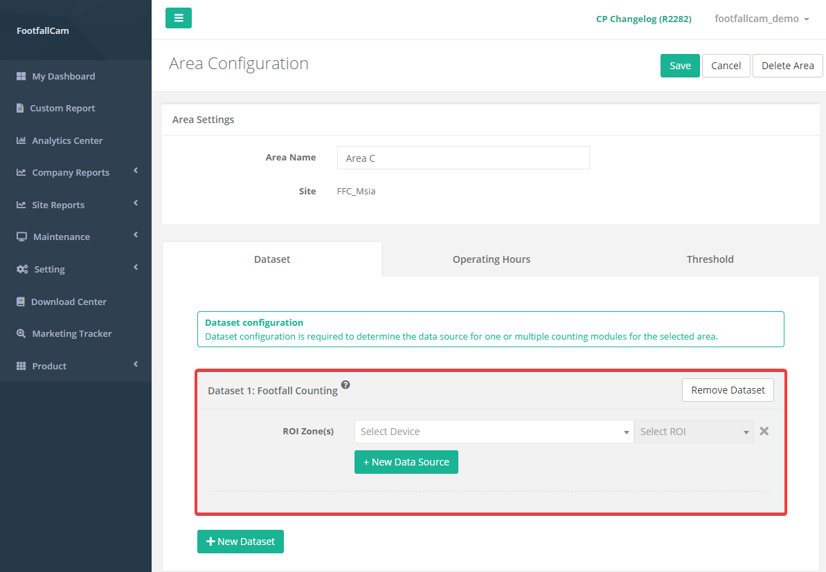
| Item | Description |
| 1. Dataset Section | Display the details of dataset. |
| 2. + New Dataset | Add new dataset section. |
| 3. Remove Dataset | Remove the dataset that you wish to remove. |
| 4. Data Source | Display the details of data source (Device & ROI). |
| 5. + New Data Source | Add new data source row. |
| 6. Remove Data Source (X) | Remove the data source that you wish to remove. |
| 7. ROI Zone(s) | Select the device of that area, then select ROI number. |
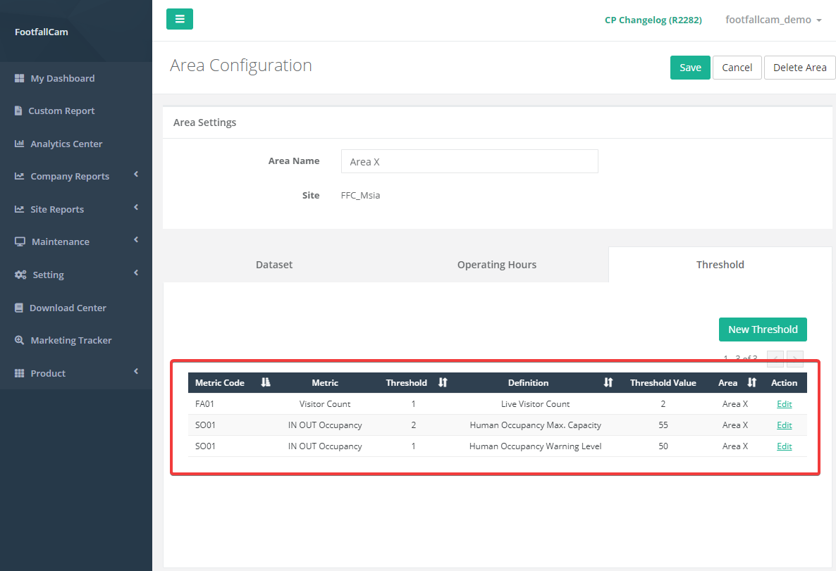
21.2.5 Threshold Configuration
Metric threshold is a feature to set a threshold to indicate the region of interest or to alert user when a threshold is breached. User can set metric threshold for area in Area Configuration or in Metric Threshold Setting, the same threshold will be shared between these two pages.
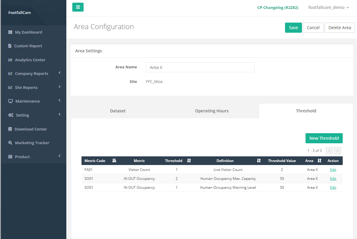
| Item | Description |
| 1. +New Threshold | Open the metric threshold settings dialog box. |
| 2. Metric Code | Display the metric code for the metric. |
| 3. Metric | Display the metric type name. |
| 4. Threshold | Display the threshold type. |
| 5. Definition | Display the metric and threshold combination. |
| 6. Threshold Value | Display the value for the metric threshold. |
| 7. Area | Display the area name that the threshold applied to. |
| 8. Action | To access the metric threshold setting form. |
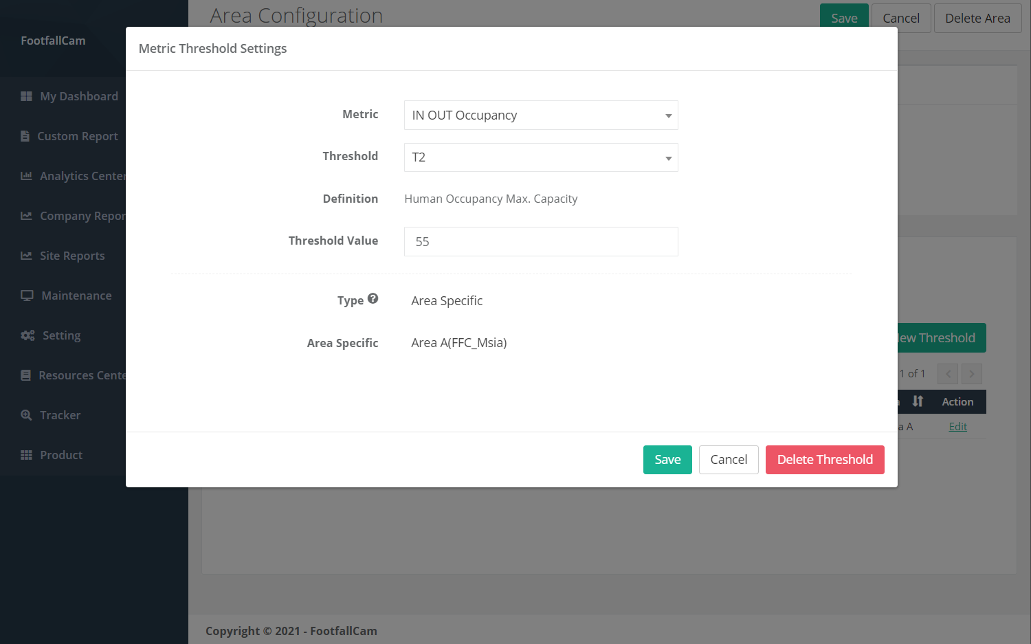
21.2.5.1 Create New Threshold
STEP 1 - Click New Threshold to trigger the Metric Threshold Setting pop up.
STEP 2 - Fill in relevant information for the required fields and click on the Save button.
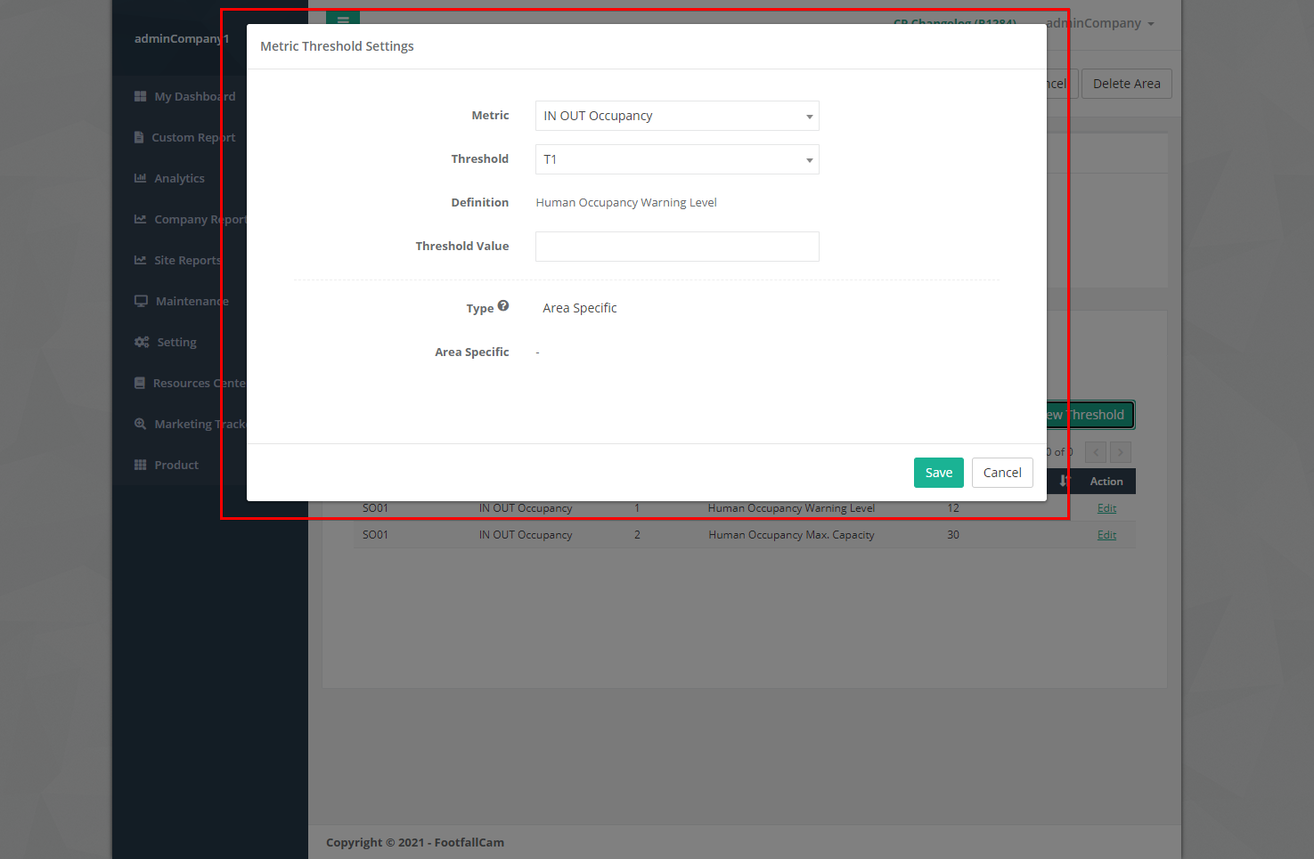
| Item | Description |
| 1. Metric | Select the metric type. |
| 2. Threshold | Select the threshold type. |
| 3. Definition | Display the definition for the selected metric type and threshold type set in Metric threshold definition. |
| 4. Threshold Value | The value for the metric threshold. |
| 5. Type | Display the type of the threshold level, which is Area Specific. |
| 6. Area Specific | The area that the threshold is applied to. |
| 7. Save Button | Save the metric threshold settings. |
| 8. Cancel Button | Close the metric threshold settings dialog box. |
21.2.5.2 Manage Threshold
STEP 1 - Navigate to the threshold you wish to manage and click the Edit button.
STEP 2 - Update the field(s) you wish to update and click on Save button to save the changes.
21.2.5.3 Delete Threshold
STEP 1 - Navigate to the threshold you wish to delete and click the Edit button.
STEP 2 - Click on Delete button to remove the metric threshold. The deleted metric threshold will no longer be reflected in the table in Threshold at Area Configuration page and the table in Metric Threshold Setting.
21.2.6 Operating Hour Configuration
Operating hour is the operation time where the area will be operational and the device would be counting. The operating hour of the area can be setup in the Operating Hours
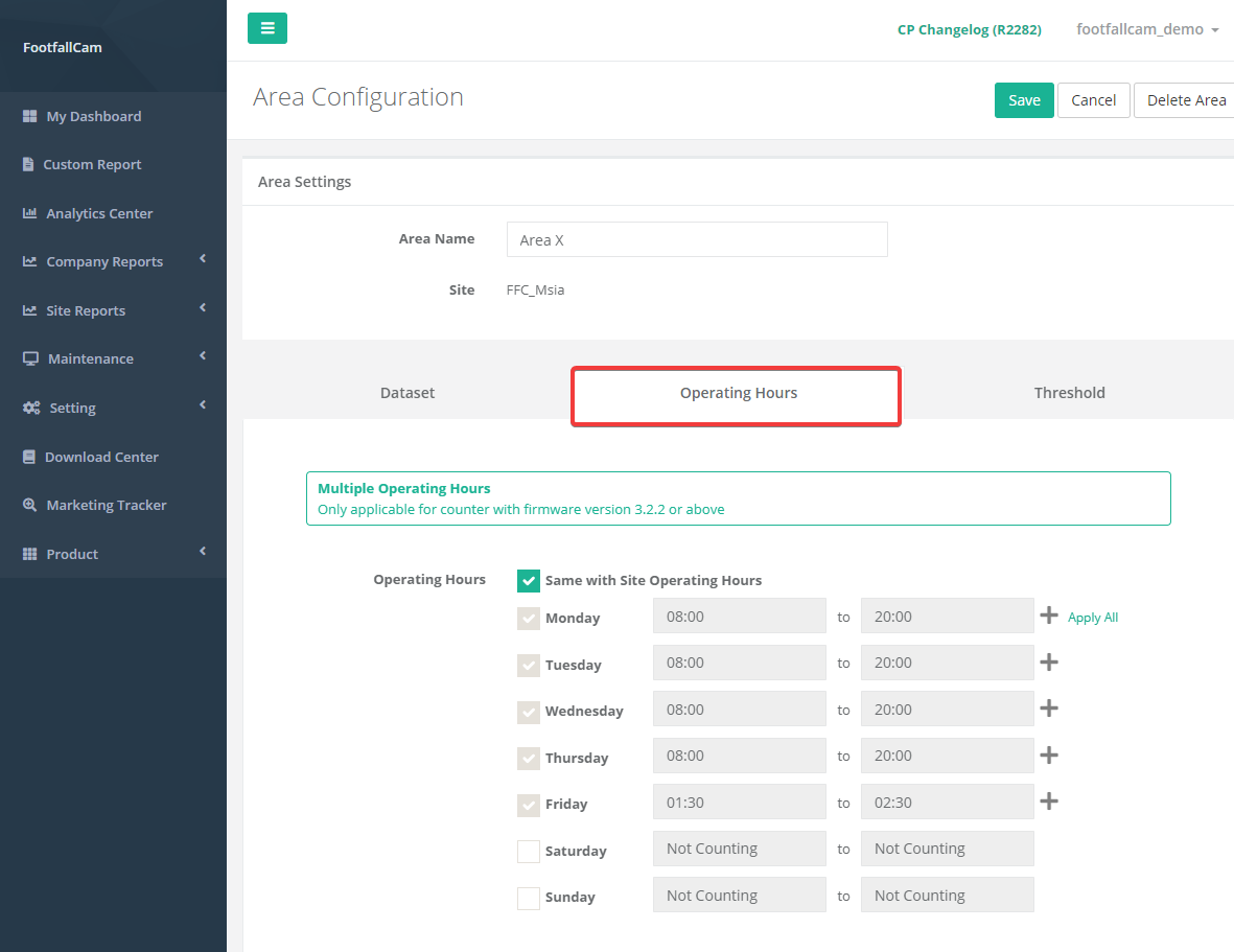
The area operating hours could be set the same with the site by ticking the Same with Site Operating Hours checkbox. If the operating time of the area is different with the site. The time can be set manually for each day with the checkbox for the day being ticked meaning the counter would be operating on that day and uncheck for off days. The time for each day could also be set depending on the site operational needs.
21.3 Area Group Configuration
STEP 1 - Access to FootfallCam Analytic Manager V9™: http://v9.footfallcam.com via Google Chrome.
STEP 2 - Click Setting > Area to access the Area List page.
| Item | Description |
| 1. Area Name | Display the area name. |
| 2. Area Group | Display the area group. |
| 3. Site | Display the site of the area. |
| 4. Type of Space | Display the type of space of the area. |
| 5. Location | Display the location of the area. |
| 6. Action | To access the Area Configuration page for the setting. |
21.3.1 Create New Area Group
STEP 1 - Access to FootfallCam Analytic Manager V9™: http://v9.footfallcam.com via Google Chrome.
STEP 2 - Click Setting > Area to access the Area List page.
STEP 3 - We will start by creating a child area. Click + New Area button to create a new area.
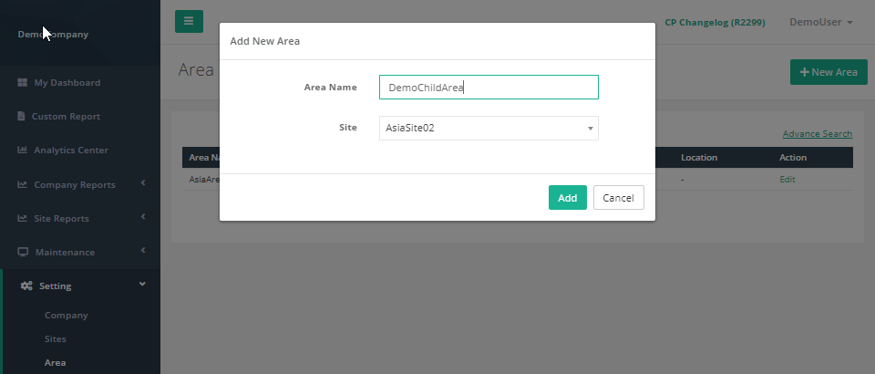 STEP 4 - Fill in relevant information for the required fields.
STEP 5 - Click Add button to add the new area. It will be redirect to Area Configuration page.
STEP 6 - Complete the process by entering all the required fields in Dataset tab (Refer to Section 21.2.4 Dataset Configuration for Dataset setting and Section 21.2.5 Threshold Configuration for metric threshold setting).
 STEP 7 - Click on Save button to create the area.
| Field | Description |
| 1. Area Name | Enter your preferred name of the area. |
| 2. Site | Select the Site to add the area. |
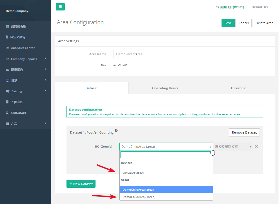
STEP 8 - Next, we will create a parent area. Click + New Area button to create a new area.
STEP 9 - Fill in relevant information for the required fields. The parent area needs to be under the same site as the child area for the area grouping to be functional.
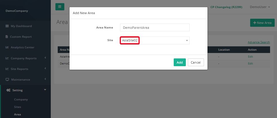 STEP 10 - Click Add button to add the new area. It will be redirect to Area Configuration page.
STEP 11 - Complete the process by entering all the required fields in Dataset tab (Refer to Section 21.2.4 Dataset Configuration for Dataset setting and Section 21.2.5 Threshold Configuration for metric threshold setting). Areas that are qualified to become child area will be displayed in the dropdown menu.
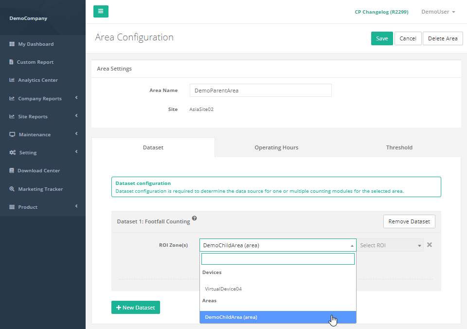
STEP 12 - Click on Save button to create the area. The parent area is not successfully created. Parent area will "own" all the devices allocated under the child area. In this example, DemoParentArea will now obtain data from device 'VirtualDevice04', because it is the parent of area 'DemoChildArea'.
21.3.2 Manage Area Group
STEP 1 - Click Setting > Area to access the Area List page.
STEP 2 - Select the the area you wish to update and click on the Edit button.
 STEP 3 - Update the relevant information and click Save to save the changes. Click Cancel if you wish to exit the page. The parent area can choose to add new device/child area, or update existing option to another device/child area.
21.3.3 Delete Area Group
The steps to delete area group is the same as area configuration. Please refer back to topic 21.2.3 Delete Area.
21.3.4 Dataset Configuration
STEP 1 - Click + New Dataset to trigger the Add Dataset pop up.
STEP 2 - Select the Counting Module and click Save button to add the dataset.
| Item | Description |
| 1. Counting Module |
Select the counting module type that you wish to add.
|
| 2. Add Button | Add new dataset section. |
| 3. Cancel Button | Close the add dataset dialog box. |
21.3.4.1 Footfall Counting
| Item | Description |
| 1. Dataset Section | Display the details of dataset. |
| 2. + New Dataset | Add new dataset section. |
| 3. Remove Dataset | Remove the dataset that you wish to remove. |
| 4. Data Source | Display the details of data source (Device & ROI). |
| 5. + New Data Source | Add new data source row. |
| 6. Remove Data Source (X) | Remove the data source that you wish to remove. |
| 7. ROI Zone(s) | Select the device of that area, then select ROI number. |
21.3.5 Threshold Configuration
The steps to setup area group threshold configuration is the same as area configuration. Please refer back to topic 21.2.5 Threshold Configuration.
21.3.6 Operating Hour Configuration
The steps to setup area group operating hour is the same as area configuration. Please refer back to topic 21.2.6 Operating Hour Configuration.
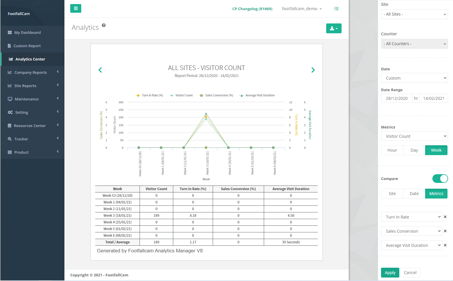
21.4 Analytics Center
After area configuration, the analysis for the area counting data can view in Analytics Center. This section focuses on the steps to setup area analytics in Analytics Center.
STEP 1 - Access to FootfallCam Analytic Manager V9™: http://v9.footfallcam.com via Google Chrome.
STEP 2 - Click Analytics Center at the left toolbar to access Analytics page.
STEP 3 - Select Area at Type field at the Options toolbar, update the following field and click Apply.
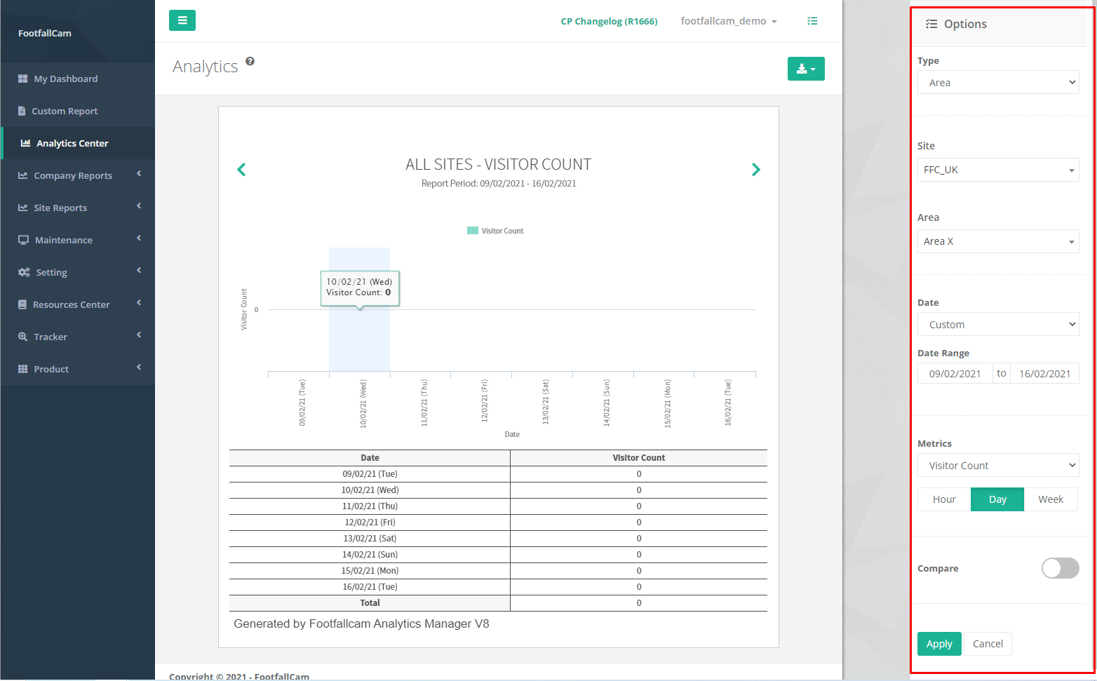
| Field | Description |
| 1. Type | Select Area to view Area counting analysis. |
| 2. Site | Select the site to be displayed. |
| 3. Area | Select the area to be displayed. |
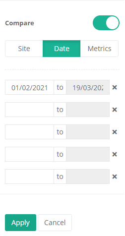
| 4. Date | Select the date range type to be displayed. |
| 5. Date Range | Update the date range for custom date. |
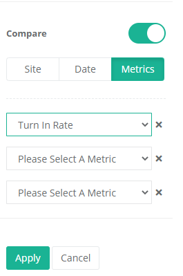
| 6. Metric | Select the metric to be displayed. |
| 7. Aggregation | Select the aggregation by hour, day or week. |
| 8. Compare | Indicator to allow comparison. |
STEP 4 - Toggle the Compare indicator to allow comparison. Select the comparison type and update the fields accordingly and click Apply.
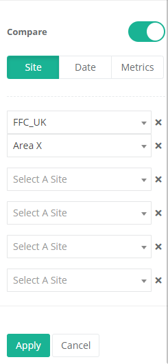 |
 |
 |
| Compare site. Select the site and respective area for comparison. |
Compare Date. Select the date range for comparison. |
Compare Metrics. Select the metrics for comparison. |
STEP 5 - View the analysis graph at the middle of the analytics page.
Chapter 23: Electronic Shelf Label (ESL) Configuration
23.1 Electronic Shelf Label
23.1.1 Brand and Category of the product
Products can be categorised according to brand and category. Brand can be used as a filter for the products tagged to it. The brand and the category need to be created before the product can tag to them. This section focuses on the creation and management of brand and category of product.
23.1.1.1 Create New Brand
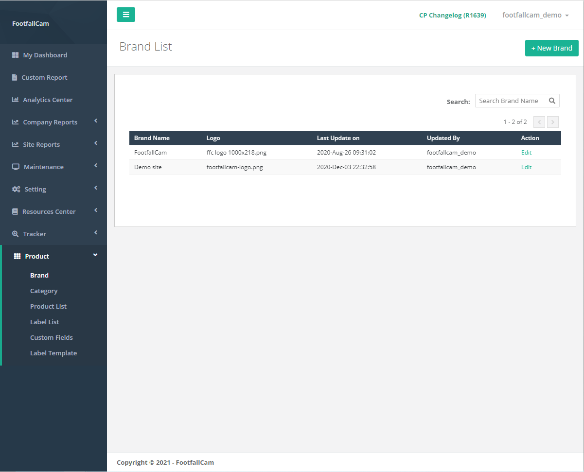
STEP 1 - Access to FootfallCam Analytic Manager V9™: http://v9.footfallcam.com via Google Chrome.
STEP 2 - Click on Product > Brand to access the Brand List page.
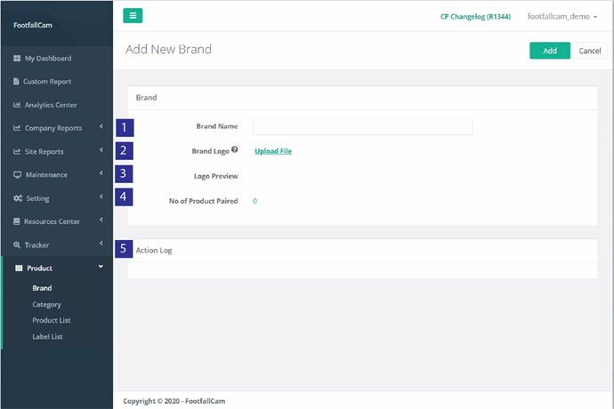
STEP 3 - Click on + New Brand button to access the Create New Brand page.
STEP 4 - Complete the process by entering all the required fields and click on Add button.
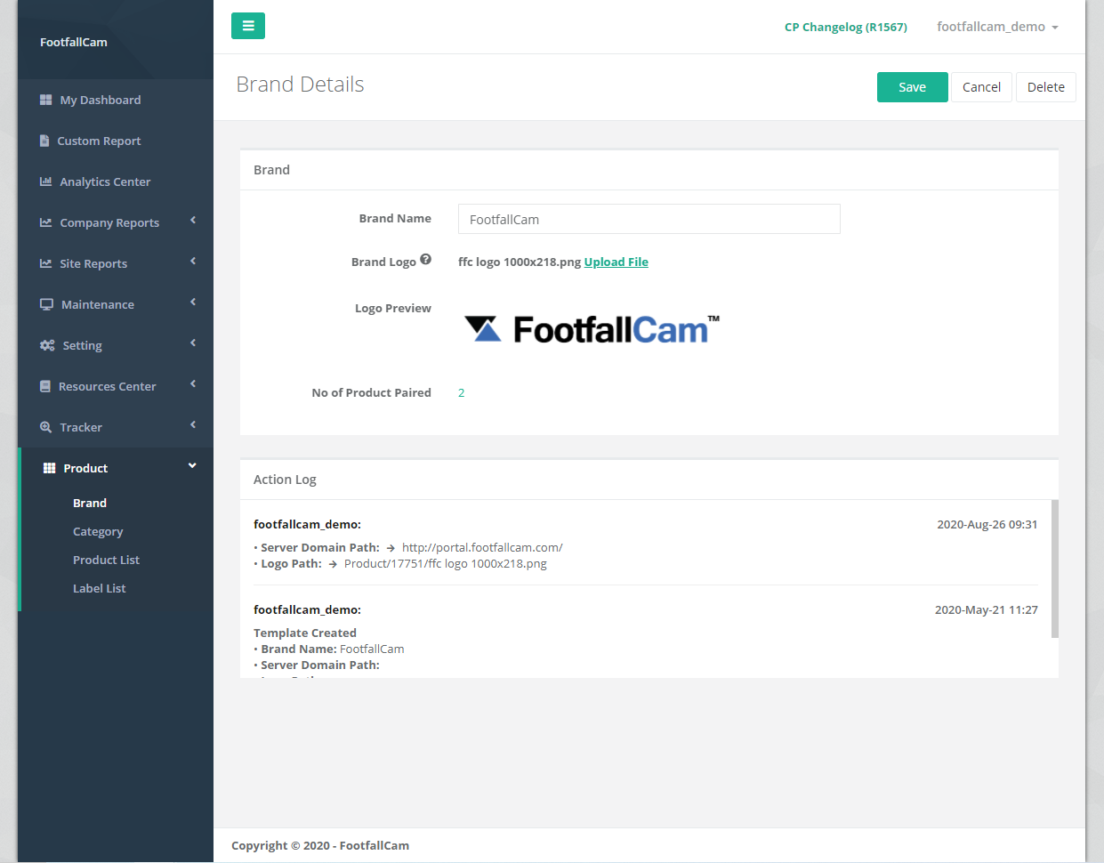
|
Item |
Description |
|
1. Brand Name |
Enter a preferred brand name. |
|
2. Brand Logo |
Upload brand logo in .png, .jpeg, or .jpg format. (Info: Logo inserted will be display on ESL.) |
|
3. Logo Preview |
Brand Logo preview of uploaded brand logo |
|
4. No of Product Paired |
Total number of product(s) paired with the brand and click the number link to direct to filtered out product(s) paired with the brand list |
|
5. Action Log |
Log all changes made by user(s) with time stamp |
23.1.1.2 Manage Brand
STEP 1 - Click on Product > Brand to access the Brand List page.
STEP 2 - Select the brand to manage and click on Edit button.
STEP 3 - Update the fields and click Save button to save the update.
23.1.1.3 Delete Brand
STEP 1 - Click on Product > Brand to access the Brand List page.
STEP 2 - Select the brand to manage and click on Edit button.
STEP 3 - Complete the process by click on the Delete button at the top-right of the page.
23.1.1.4 Create New Category
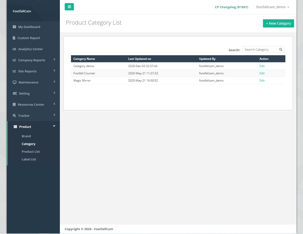
STEP 1 - Access to FootfallCam Analytic Manager V9™: http://v9.footfallcam.com via Google Chrome.
STEP 2 - Click on Product > Category to access the Category List page.
STEP 3 - Click on + New Category button to access the Create New Category page.
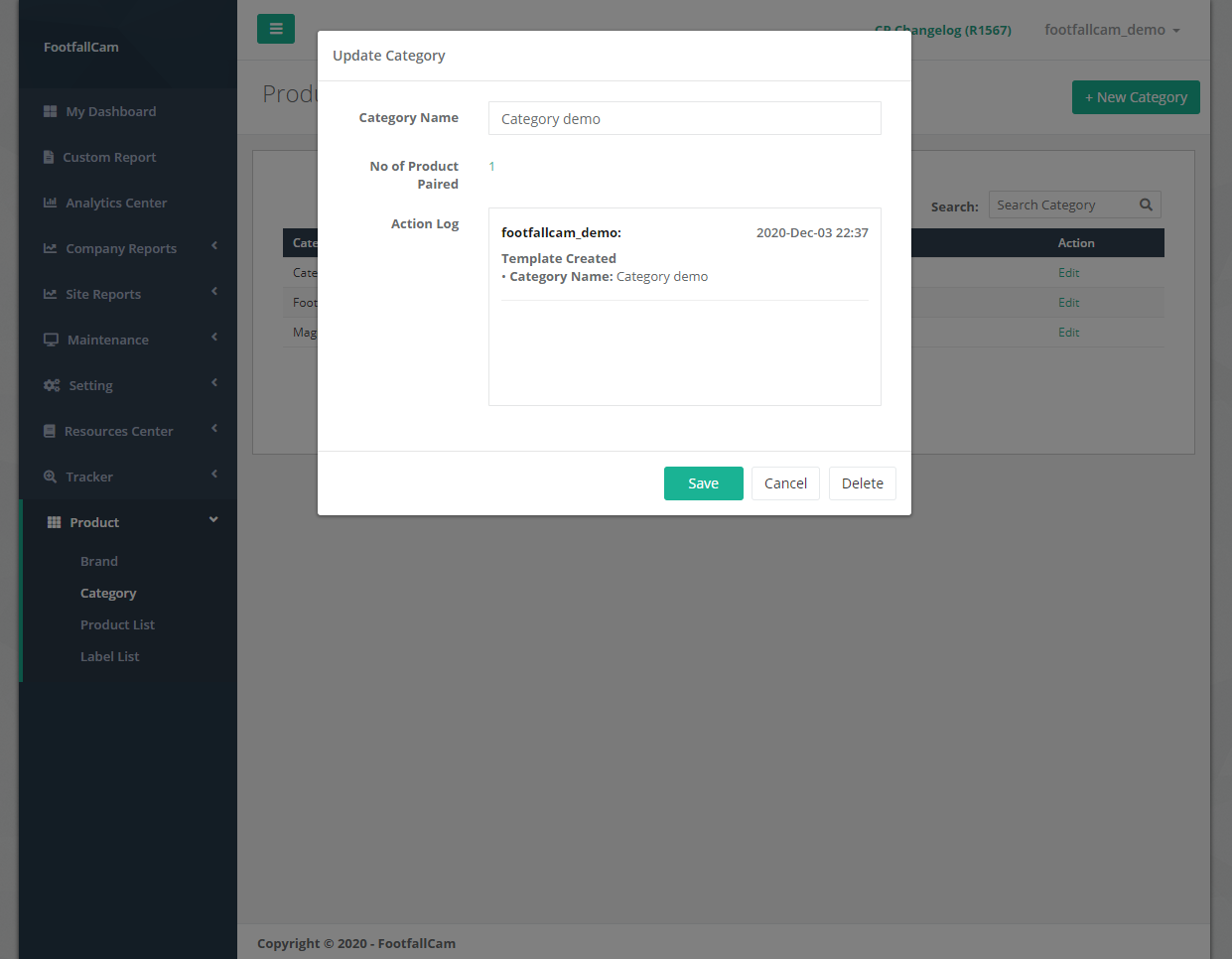
STEP 4 - Complete the process by entering all the required fields and click on Add button.
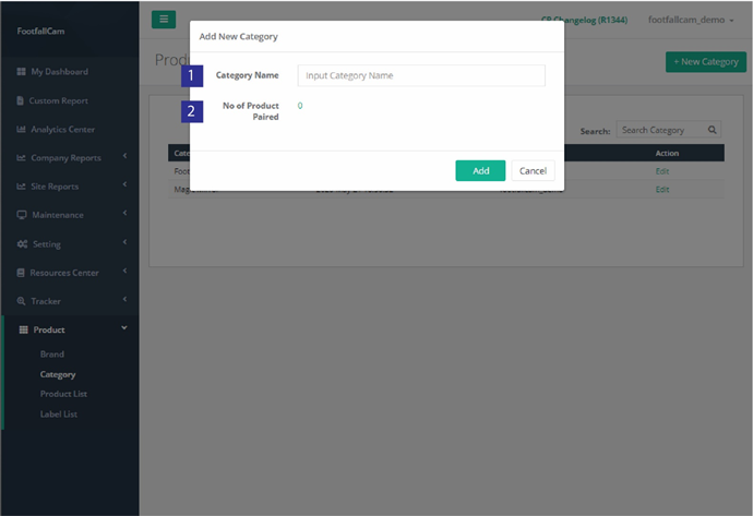
|
Item |
Description |
|
1. Category Name |
Enter a preferred category name. |
|
2. No of Product Paired |
Total number of product(s) paired with the category and click the number link to direct to filtered out product(s) paired with the category list |
23.1.1.5 Manage Category
STEP 1 - Click on Product > Category to access the Category List page.
STEP 2 - Select the category to manage and click on Edit button.
STEP 3 - Update the Category Name and click Save button to save the update.
23.1.1.6 Delete Category
STEP 1 - Click on Product > Category to access the Category List page.
STEP 2 - Select the category to manage and click on Edit button.
STEP 3 - Complete the process by click on the Delete button at the bottom of the pop-out page.
23.1.2 Create Custom Field List
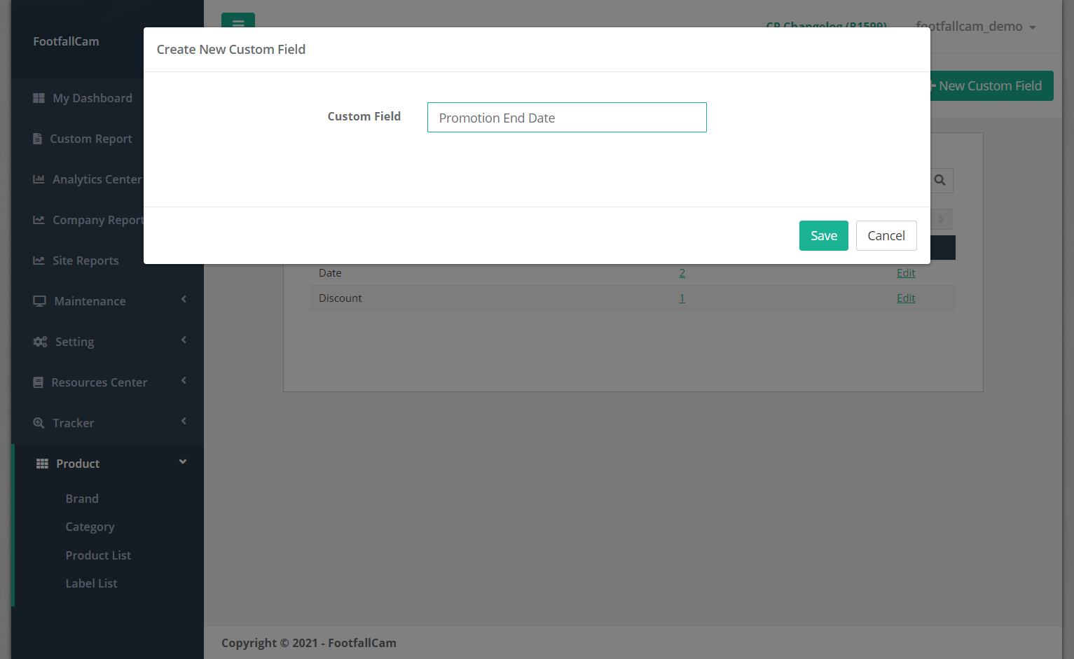
Sometimes there are info to show on the ESL tag but vary by product, for example promotion end date. It would be troublesome to create different label template due to the promotion end date are fixed text in label template. Custom field feature is a solution to this as it enables to create custom field that accept different value per product. The ESL tag can update accordingly using the same template.
23.1.2.1 Create New Custom Field
STEP 1 - Access to FootfallCam Analytic Manager V9™: http://v9.footfallcam.com via Google Chrome.
STEP 2 - Click on Product > Custom Fields to access the Custom Field List page.
STEP 3 - Click on + New Custom Field button at top right corner to trigger the Create New Custom Field pop up.
STEP 4 - Complete the process by entering preference custom field name and click on Save button.
23.1.2.2 Manage Custom Field
STEP 1 - Click on Product > Custom Fields to access the Custom Field List page.
STEP 2 - Select the custom field to manage and click on Edit button.
STEP 3 - Update the Custom Field Name and click Save button to save the update.
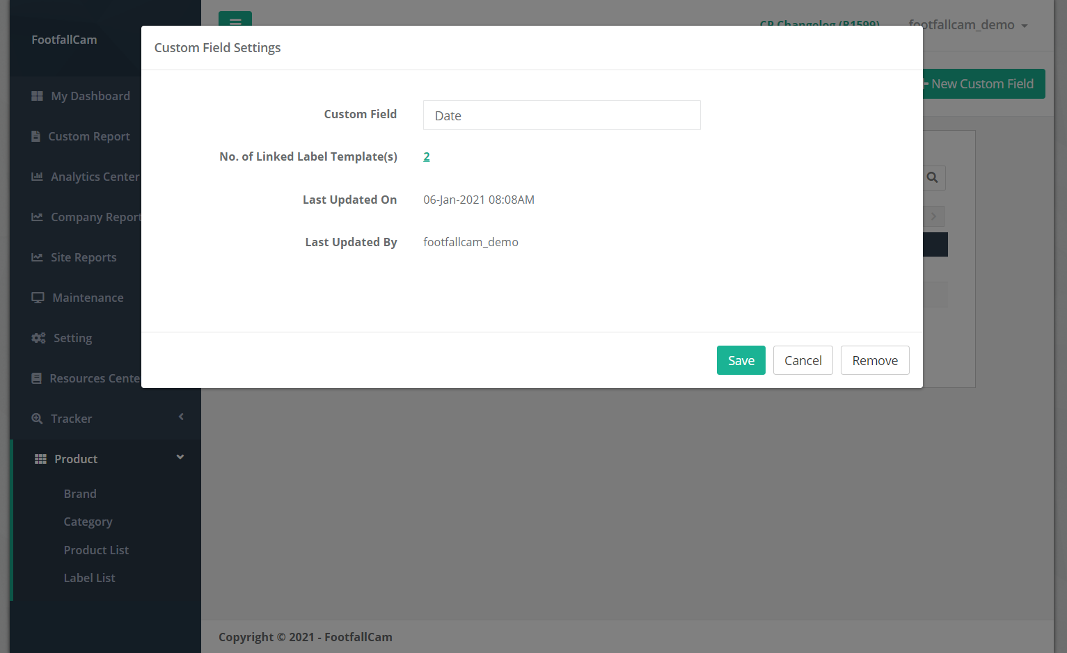
23.1.2.3 Delete Custom Field
STEP 1 - Click on Product > Custom Fields to access the Custom Field List page.
STEP 2 - Select the custom field to manage and click on Edit button.
STEP 3 - Complete the process by click on the Remove button at the bottom of the pop-out page.
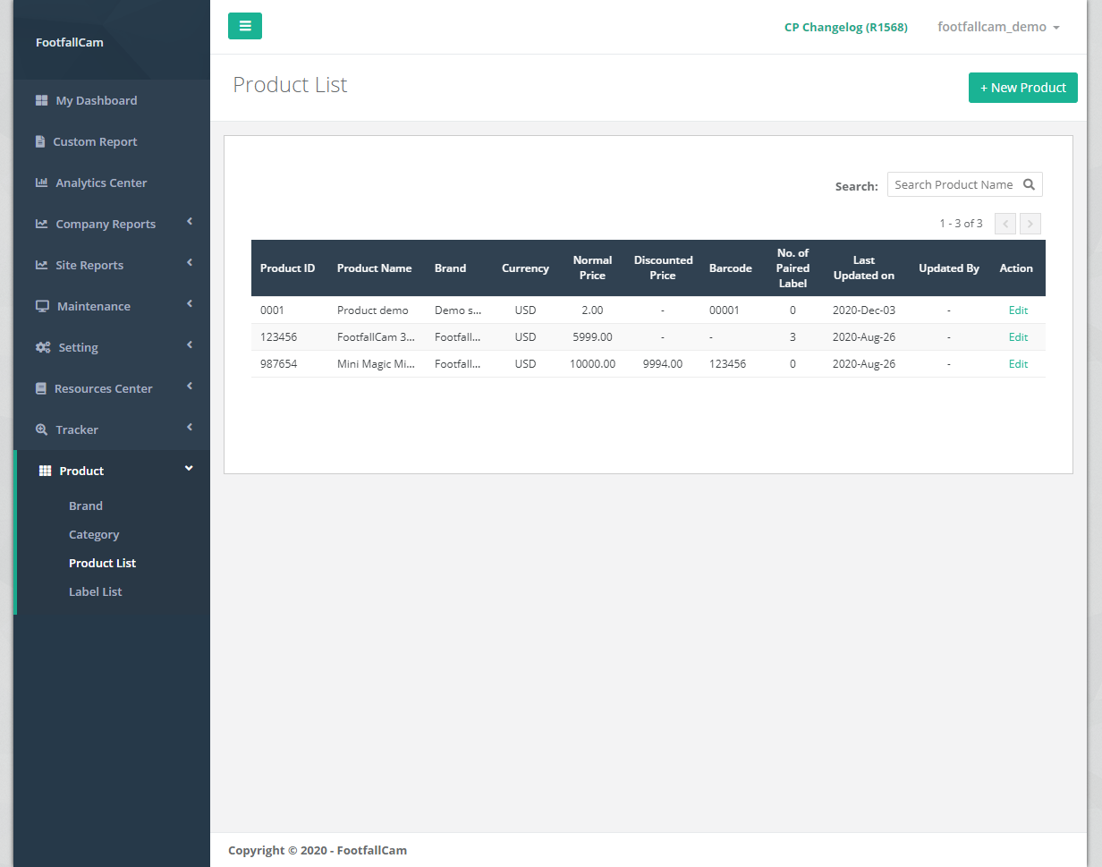
23.1.3 Create Product List
This section focuses on the creation and management of products. Information related to the product including the description, pricing, discounted price, and number of units are stored in the system to be used on ESL display.
23.1.3.1 Create New Product
STEP 1 - Access to FootfallCam Analytic Manager V9™: http://v9.footfallcam.com via Google Chrome.
STEP 2 - Click on Product > Product List to access the Product List page.
STEP 3 - Click on + New Product button to access the Create New Product page.
STEP 4 - Complete the process by entering all the required fields and click on Add button.
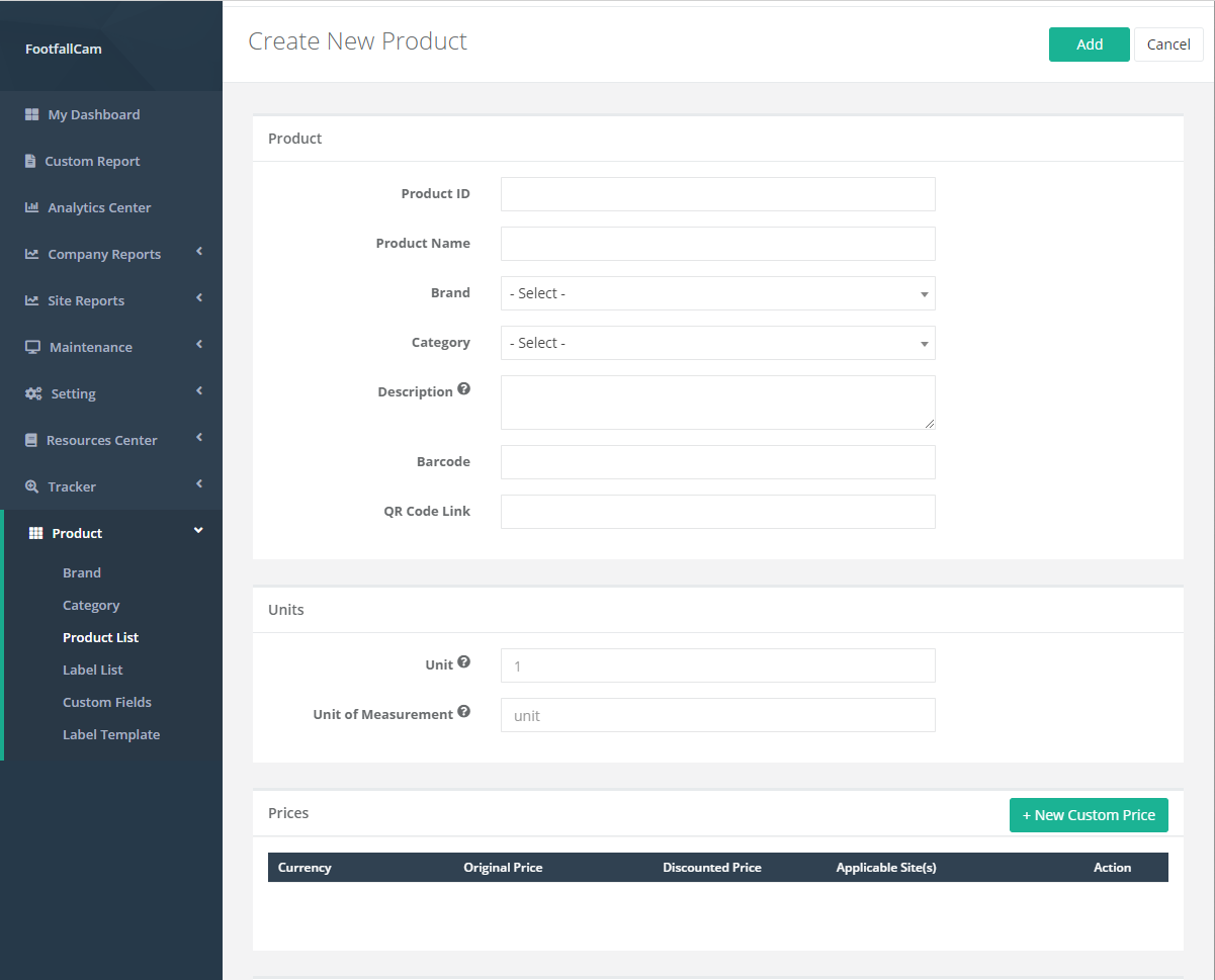
There are 6 major parts of product's details, which are product general information, units information, prices information, others information, custom fields input and action log. Below are the details of each field.
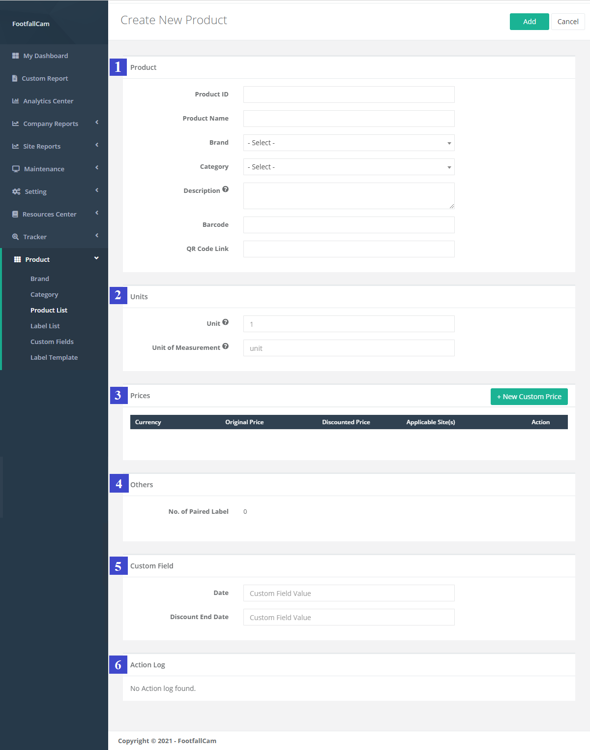
Part 1: Product General Information:
|
Item |
Description |
|
1. Product ID |
Enter a preferred product ID. |
|
2. Product Name |
Enter a preferred product name. (Info: Product Name inserted will be display on ESL.) |
|
3. Brand |
Select the product brand to pair the product to selected brand. (Info: For more information on brand, please refer to Section 23.1.2 Create Brand and Category of the product.) |
|
4. Category |
Select the product category to pair the product to selected category. (Info: For more information on Category, please refer to Section 23.1.2 Create Brand and Category of the product.) |
|
5. Description |
Enter the product description. (Info: Product description inserted will be display on ESL.) |
|
6. Barcode |
Enter the product barcode. (Info: Product barcode inserted will be display on ESL.) |
|
7. QR Code Link |
Enter the product QR code link. (Info: Product QR code inserted will be display on ESL.) |
Part 2: Product Unit Information:
|
Item |
Description |
|
1. Unit |
The number of physical units assigned to the price of the product (eg. $10 per 100g, unit = 100) (Info: Unit inserted will be display on ESL.) |
|
2. Unit of Measurement |
The physical units to quantify the product sold (eg. Metter, kg, dozen etc.) (Info: Unit of Measurement inserted will be display on ESL.) |
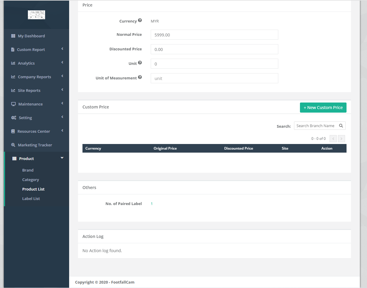
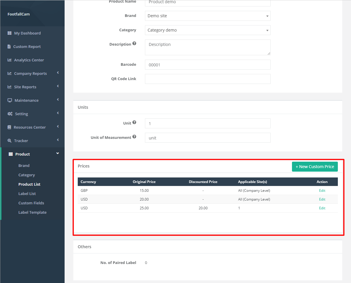
Part 3: Product Price Information:
|
Item |
Description |
|
1. Currency |
The default currency selected in company profile (Info: Default Currency will be display on ESL, please refer to FFC portal) |
|
2. Normal Price |
The normal price of the product (Info: Normal Price inserted will be display on ESL.) |
|
3. Discounted Price |
The discounted price of the product (Info: Discount Price is optional and will be display on ESL if inserted.) |
|
4. Applicable Site(s) |
Display the number of sites applied for the selected currency. If the currency is a company level price, then it is applied to all sites. |
|
5. Action |
To trigger the Custom Price pop up to manage the selected custom price. |
Part 4: Product Others Information:
|
Item |
Description |
|
1. No. of Paired Label |
Display he number of labels being paired to this product information. |
Part 5: Product Custom Field Information:
If the custom field is set up, then the list of custom field will appeared here for input. (For more information regarding custom field, please refer to Section 23.1.2 Create Custom Field List)
Part 6: Action Log:
Action Log displayed the detail of actions being done to the product page by Login User
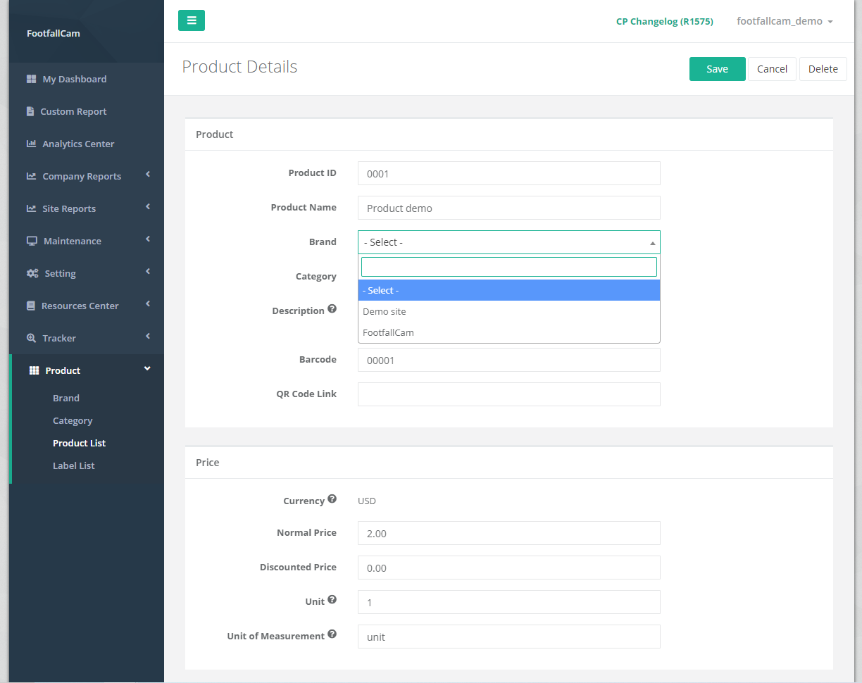
23.1.3.2 Manage Product
This section focuses on the management of product details. Product general details and pricing details can be updated if required. If a product is having promotion, the ESL label supposed to display the discounted price while after the promotion ended, the ESL label should displays the original price of the product. This can be done by updating the product pricing details Discounted Price field when the promotion started and after the promotion ended.
STEP 1 - Click on Product > Product List to access the Product List page.
STEP 2 - Select the product to manage and click on Edit button.
STEP 3 - Update the required fields and click on Save button.
23.1.3.3 Unpair Brand and Category
Product can be paired to a brand and category and it can be unpaired as well. This section focuses on the way to unpair brand or unpair category.
STEP 1 - Click on Product > Product List to access the Product List page.
STEP 2 - Select the product to manage and click on Edit button.
STEP 3 - Click the Brand field (or Category field) dropdown menu and choose - Select - to unpair the brand (or Category)
STEP 4 - Complete the process by clicking on Save button.
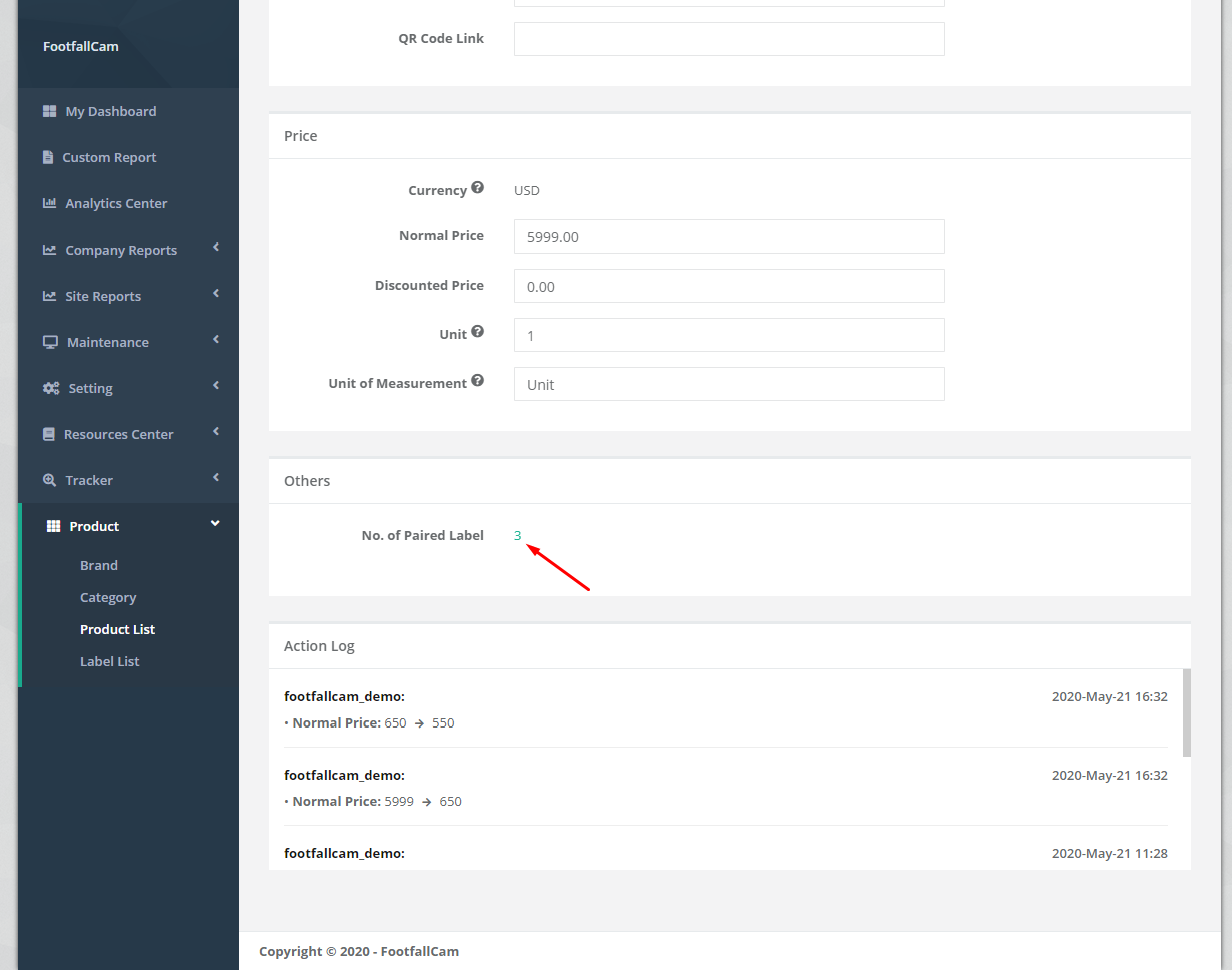
23.1.3.4 Product linked to Paired Label
The No. of Paired Label column in the Product List indicates the total number of label paired to the product. If there is at least one label paired to the product, by clicking on the No. of Paired Label field in the product details can link to the Label List to view the paired labels information.
STEP 1 - Click on Product > Product List to access the Product List page.
STEP 2 - Select the product to manage and click on Edit button.
STEP 3 - Click on the No. of Paired Label to link to Label List with paired labels information.
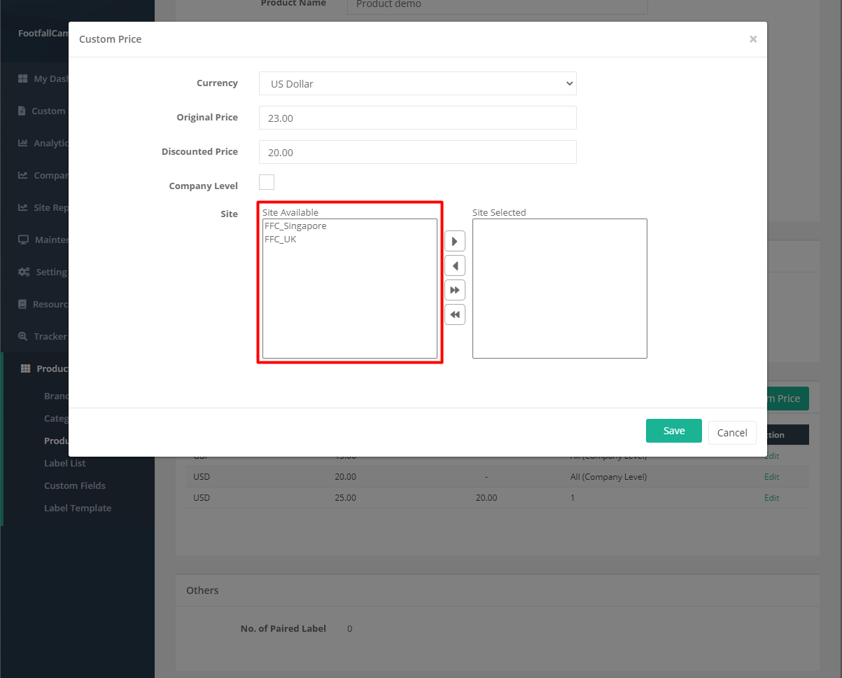
23.1.3.5 Create New Custom Price
Custom price is a feature that enable users to customise the price by site level as well as by different type of currency. A product can have only one company level custom price for each currency and it can have different site level custom prices for different sites. If the site level custom price is not defined, then company level custom price is used to display on the ESL label.
This section focuses on the creation of new custom price and next section will explain on the management of custom price for different sites.
STEP 1 - Click on Product > Product List to access the Product List page.
STEP 2 - Select the product to manage and click on Edit button.
STEP 3 - Navigate to Custom Price Section and click + New Custom Price .
STEP 4 - Fill in details, select site to apply pricing and click Save to add custom price.
STEP 5 - Complete the overall process by click on the Save button at the top-right of the page.
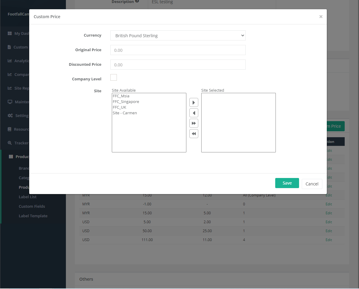
| Item | Description |
| 1. Currency | Select the currency for the custom price. |
| 2. Original Price | Input the original price with respect to the currency selected. |
| 3. Discounted Price | Input the discounted price with respect to the currency selected. |
| 4. Company Level |
If the company level field is ticked, the custom price is company level custom price. Else it is site level custom price. |
| 5. Site | Select the sites to apply the custom price. |
A product can only have one company level custom price for each currency. An error message will prompt if user tried to create the second company level custom price for the same currency.
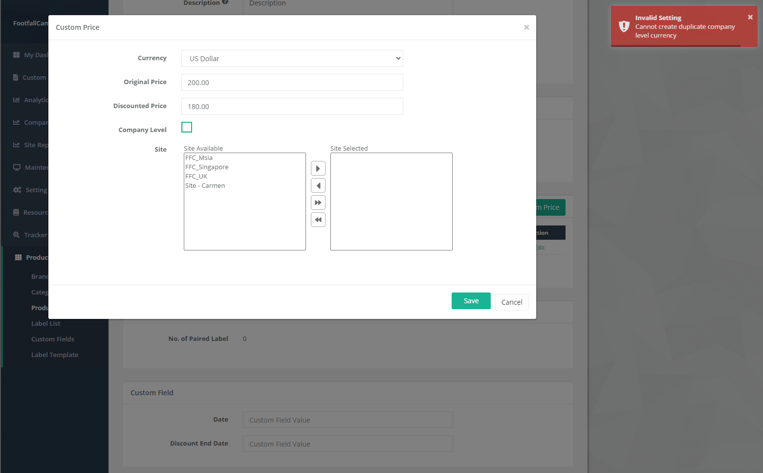
However, a product can have one company level custom price for different currency.
Each site can only have one site level custom price for the same currency. If the site already have site level custom price for the selected currency, it will not appeared in the site available field.
23.1.3.6 Manage Custom Price
This section focuses on the management of custom price for different sites to update the prices or change the site paired.
STEP 1 - Click on Product > Product List to access the Product List page.
STEP 2 - Select the product to manage and click on Edit button.
STEP 3 - Select Custom Price to manage, click Edit and configure the details and click Save to apply latest change.
STEP 4 - Complete the overall process by click on the Save button at the top-right of the page.
23.1.4 Create ESL Label template
ESL label template is the label template that will be displayed on the ESL tag. The label template can be designed and customised based on your preference.
23.1.4.1 Create New ESL Display Template
STEP 1 - Access to FootfallCam Analytic Manager V9™: http://v9.footfallcam.com via Google Chrome.
STEP 2 - Click on Product > Label Template to access the Label Template List page.
STEP 3 - Click on + New Template button to trigger the New Label Template pop up.
STEP 4 - Fill up all the required fields and click on Save button.
STEP 5 - Complete the process by click on Confirm button and go into Template Design page.
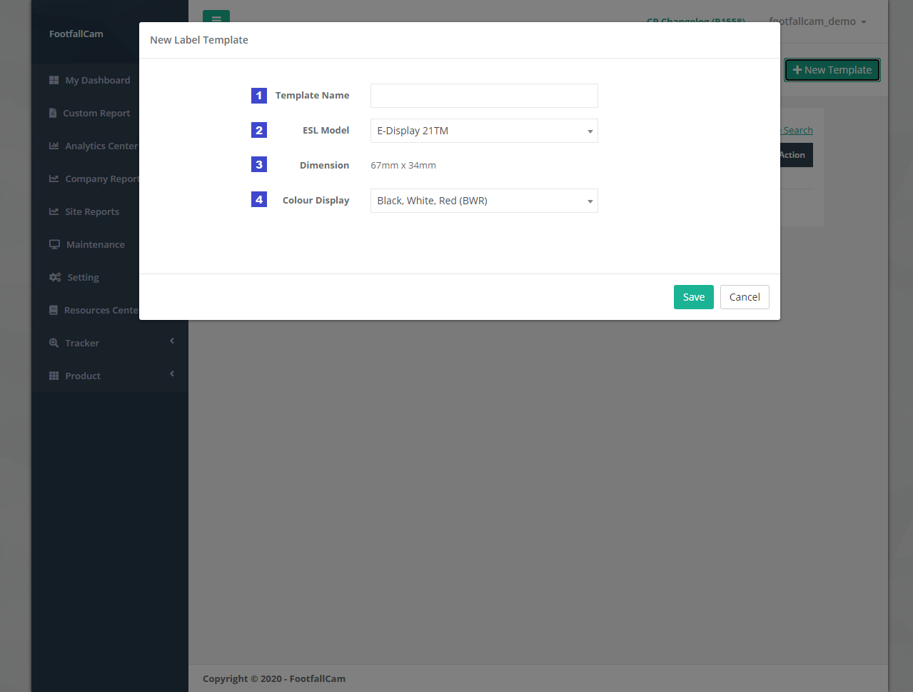
|
Item |
Description |
|
1. Template Name |
Enter a preferred template Name. |
|
2. ESL Model |
Select the ESL Model. (Info: 2 ESL Model: E-Display 21TM, E-Display 42TM) (Info: ESL model selected cannot be change in the future. ) |
|
3. Dimension |
The dimension of template display according to ESL Model selected. E-Display 21TM - 67mm x 34mm E-Display 42TM - 99mm x 84.9mm |
|
4. Colour Display |
Select the colour combination to use for template design on the colour of text, shape and border. Only the selected colour will be displayed on the ESL label tag, image with other colour will be converted to the selected colour combination. There are 3 set of colour combinations:
(Info: Colour display selected cannot be change in the future. ) |
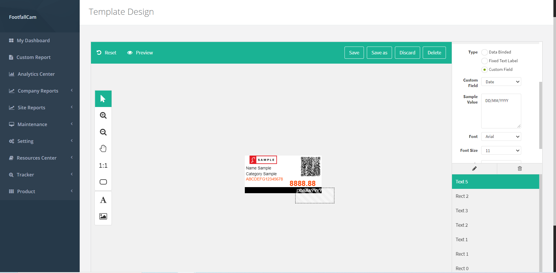
23.1.4.2 Design Label Template
ESL label template design is a feature that enables customisation on the design of the template according to own preference and purposes.
STEP 1 - Click on Product > Label Template to access the Label Template List page.
STEP 2 - Select the Label Template to manage and click on the Edit button at the Action column.
STEP 3 - Design the template as your preference.
STEP 4 - Complete the process by click on Save button.
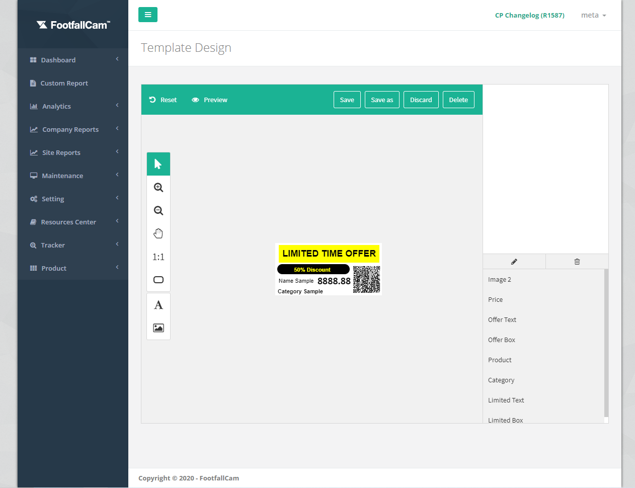
Toolbar on top:
|
Item |
Description |
|
1. Reset |
To restored the template design to last saved version. |
|
2. Preview |
To display the template shown on the ESL label tag. (Info: The display on ESL label will be the same as per preview) |
|
3. Save |
To save the updated template design as latest version and return to Label Template List. |
|
4. Save as |
To save the latest template design as a new template without changing the existing template. |
|
5. Discard |
To return to Label Template List without save. |
|
6. Delete |
To delete the label template design. (Info: Label Template selected MUST be unpaired with ESL in order to perform this action.) |
Toolbar on the left:
|
Item |
Description |
|
1. Select |
To select item on the canvas. |
|
2. Zoom In |
To zoom in the canvas for design. (Info: Press Ctrl + for zoom in shortcut key.) |
|
3. Zoom Out |
To zoom out the canvas for design. (Info: Press Ctrl - for zoom out shortcut key.) |
|
4. Drag Canvas |
To move the canvas for design. (Info: Hold space bar and drag for shortcut key.) |
|
5. Reset Canvas Zoom |
To reset canvas to original size (reset zoom). |
|
6. Rectangle |
To draw a rectangle. |
|
7. Text |
To add text for the template design. There are 2 text type:
|
|
8. Custom Image |
To add custom image for the template design. There are 2 image type:
|
Toolbar on the right:
|
Item |
Description |
|
1. General |
General information of item on template design. (Info: This field will be shown when an item is selected and will be hide when no item is selected.) |
|
2. Text / Default Style |
Text information or style information. (Info: This field will be shown when an item is selected and will be hide when no item is selected.) |
|
3. Rename |
Rename the item on the template design to your preferred name. A pop up will be shown to rename. |
|
4. Delete |
Delete the selected item. |
|
5. Item List |
The list and order of items in the template. Drag the item to arrange the sequence. |
23.1.4.3 Manage Label Template
This section focuses on the management of the label templates created. The details of the template are displayed in the template list. The template design can be preview by mouse over to the preview icon and can be updated if required.
STEP 1 - Click on Product > Label Template to access the Label Template List page.
STEP 2 - Select the Label Template to manage and click on the Edit button at the Action column.
STEP 3 - Update the template design as your preference.
STEP 4 - Complete the process by click on Save button.
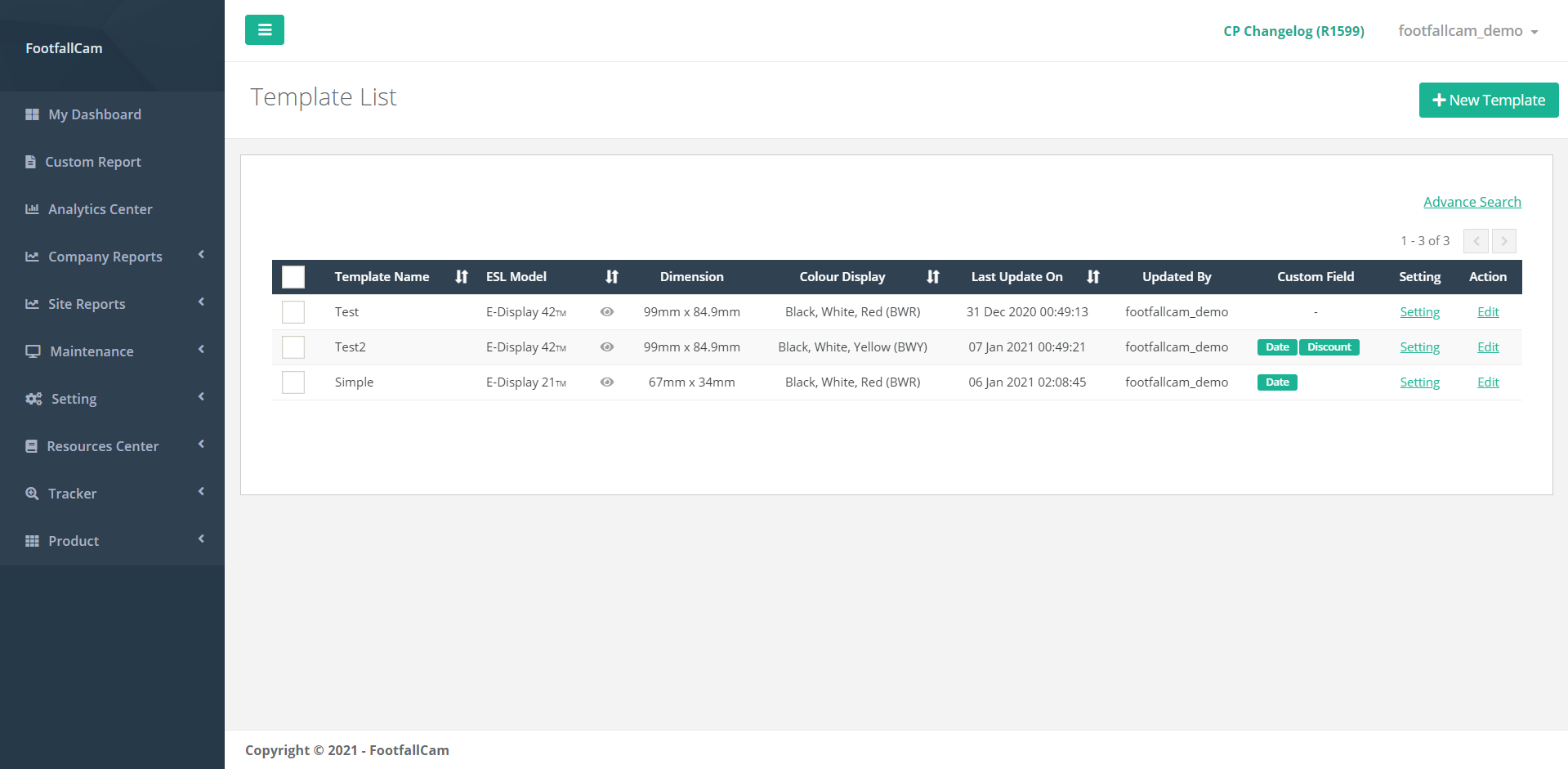
|
Item |
Description |
|
1. Template Name |
Name of the template. |
|
2. ESL Model |
ESL model of the template. (Info: 2 ESL Model: E-Display 21TM, E-Display 42TM) |
|
3. Preview |
Preview the template by mouse over to the icon. |
|
4. Dimension |
Dimension of the template according to the ESL model selected. (Info: E-Display 21TM - 67mm x 34mm ; E-Display 42TM - 99mm x 84.9mm ) |
|
5. Colour Display |
The colour combination of the template. |
|
6. Last Update On |
Last template updated date time |
|
7. Updated By |
Last login user to update the template |
|
8. Custom Field |
The custom field paired in the template. |
|
9. Setting |
To trigger Label Template Setting Pop up to manage selected template. |
|
10. Action |
To trigger Template Design page to update the template design. |
23.1.4.4 Unpair Custom Field
STEP 1 - Click on Product > Label Template to access the Label Template List page.
STEP 2 - Select the Label Template to manage and click on the Edit button at the Action column.
STEP 3 - Select the custom field to be unpaired and click on the delete (dustbin icon) and the right toolbar.
STEP 4 - Complete the process by click on Save button.
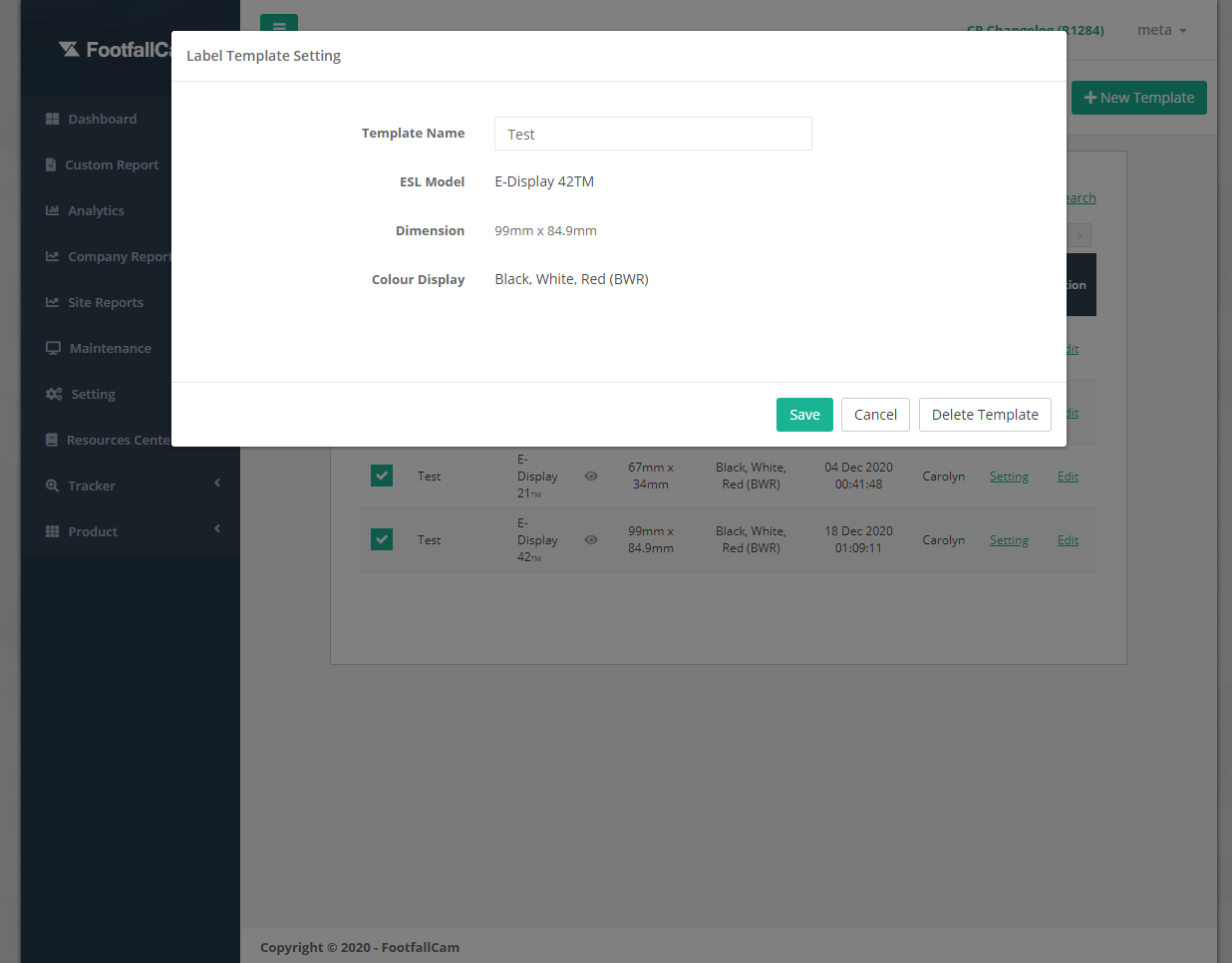
23.1.4.5 Delete Label Template
STEP 1 - Click on Product > Label Template to access the Label Template List page.
STEP 2 - Select the label template to manage and click on Setting button.
STEP 3 - Complete the process by click on the Delete Template button.
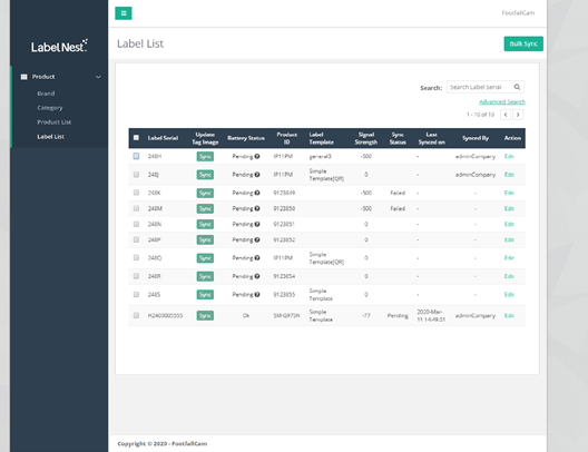
23.1.5 Manage Label
After the ESL pairing process is completed, the ESL label is displayed in Label List. The label in the label list shows the information of the ESL and can be updated accordingly.
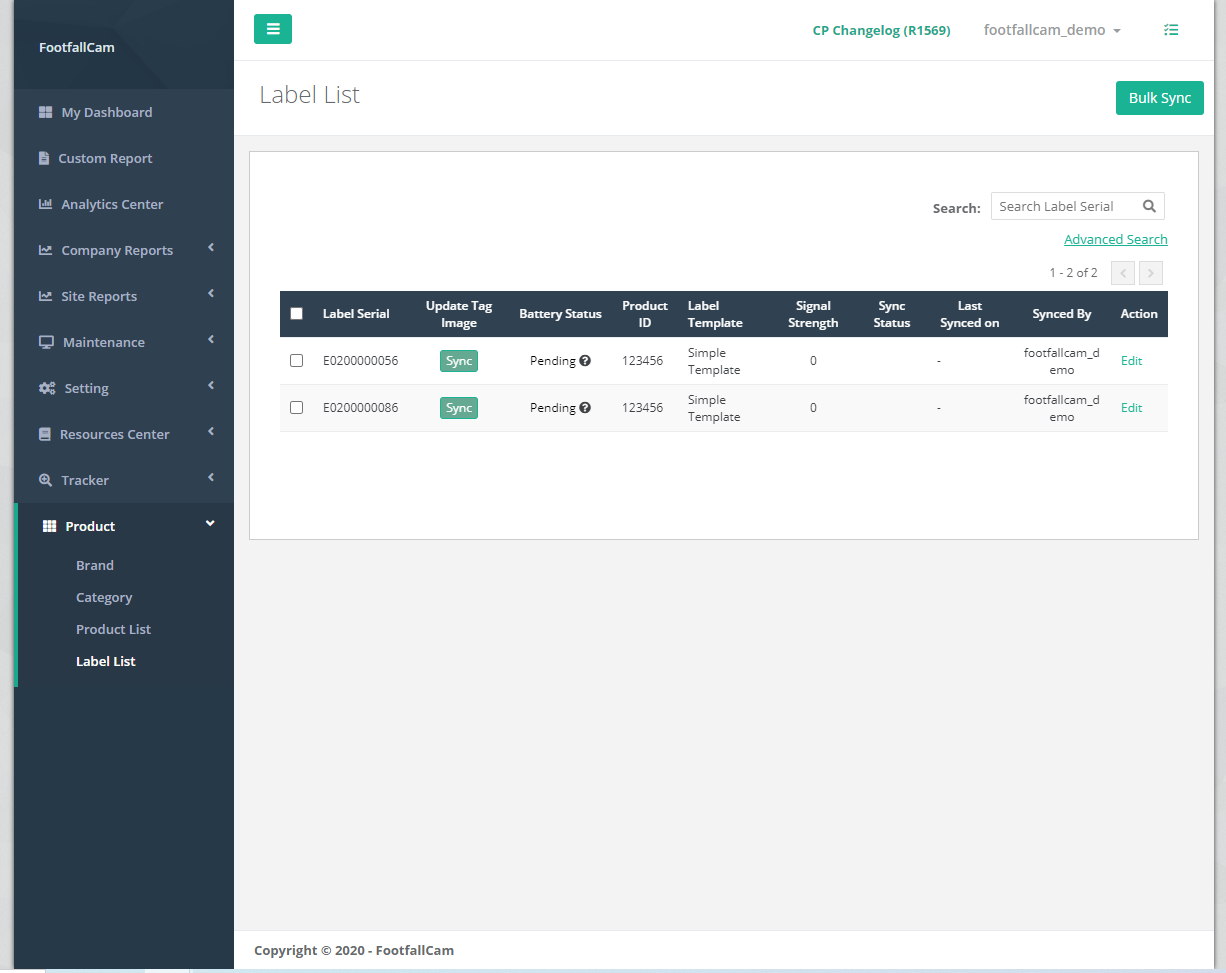
23.1.5.1 Label Display
STEP 1 - Access to FootfallCam Analytic Manager V9™: http://v9.footfallcam.com via Google Chrome.
STEP 2 - Click on Product > Label List to access the Label List page.
|
Item |
Description |
|
1. Label Serial |
The Unique Serial Number for the ESL Tag (Info: Label Serial is uploaded by scanning the serial barcode of the ESL) |
|
2. Update Tag Image |
Click to update the detail changes onto ESL Tag |
|
3. Battery Status |
Show ESL battery status (Info: At Low status recommend to change ESL batteries.) |
|
4. Product ID |
Product ID detail that is bound to the ESL Tag (Info: Selected product ID detail will be displayed on ESL Tag.) |
|
5. Label Template |
Type of label template selected for the ESL Tag (Info: Selected label template will be displayed on ESL Tag.) |
|
6. Signal Strength |
The Signal connection between the ESL Tag and Base Station |
|
7. Sync Status |
Update tag image status (Info:3 status: Synced, Pending, Request Sent) |
|
8. Last Sync On |
Last successfully image updated time |
|
9. Last Synced By |
Last Login User to Sync the Label |
|
10. Action |
To trigger Label Setting Pop up to manage selected Label. |
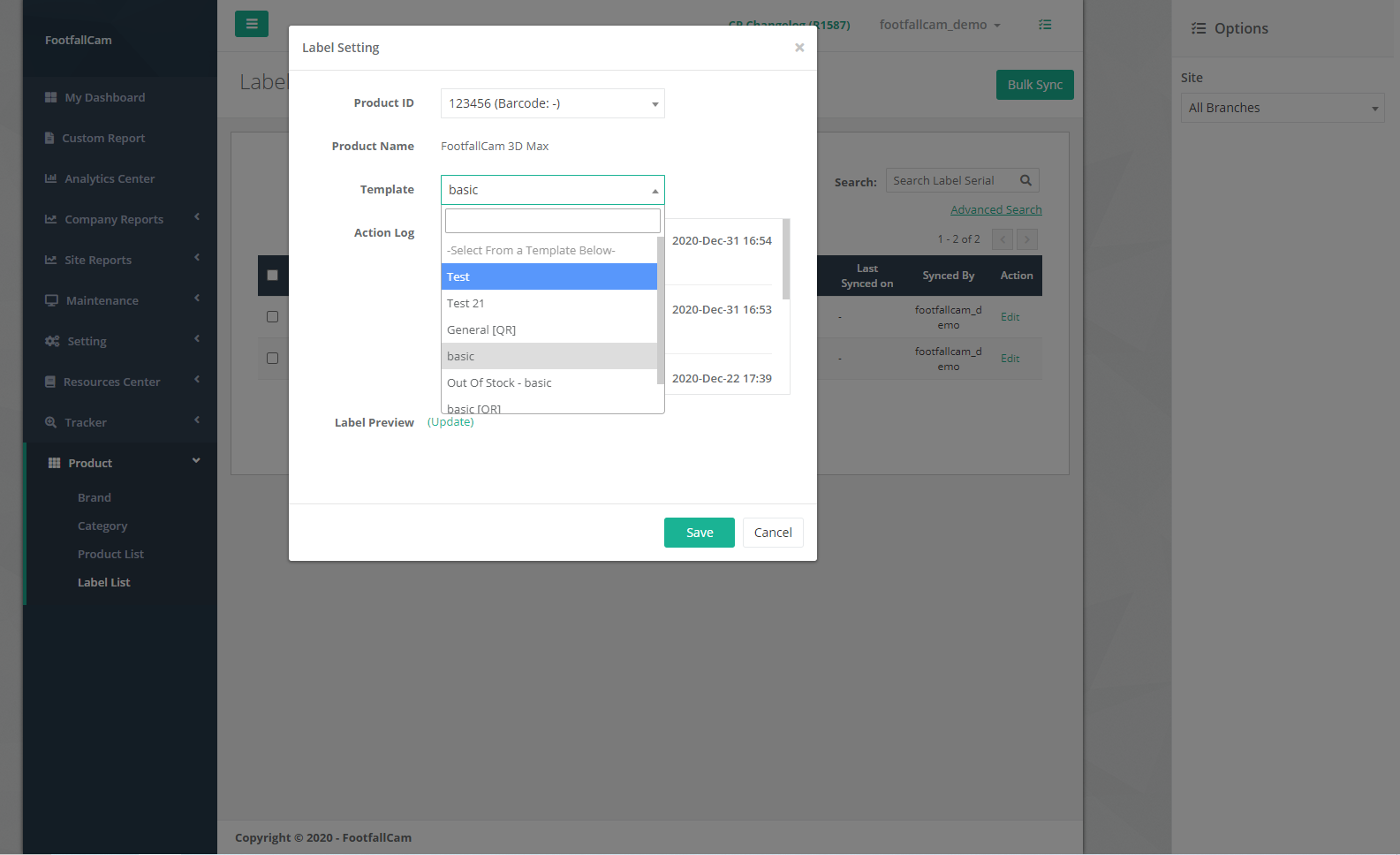
23.1.5.2 Manage Label Setting
STEP 1 - Access to FootfallCam Analytic Manager V9™: http://v9.footfallcam.com via Google Chrome.
STEP 2 - Click on Product > Label List to access the Label List page.
STEP 3 - Select the label to manage and click on Edit button.
STEP 4 - Select Product ID and Template then click Preview Template to preview the template.
STEP 5 - Complete the process by clicking on Save button.
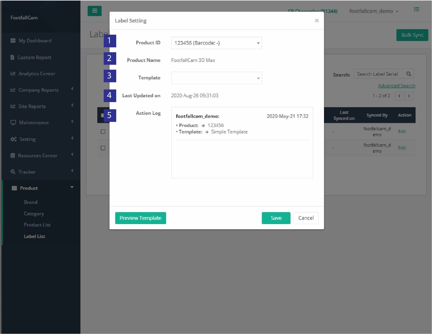
|
Item |
Description |
|
1. Product ID |
The Product's Product ID to be bind with the selected label (Info: Product ID's Product Detail will be displayed on ESL Tag.) |
|
2. Product Name |
The selected product ID name |
|
3. Template |
The type of Template Design Available for the selected Label (Info: Template Design will be displayed on ESL Tag.) |
|
4. Last Updated On |
Latest time where there is change(s) in the Label Setting. |
|
5. Action Log |
The details of action being done to the label setting by Login User |
23.1.5.3 Unpair Label Template
Label can be paired to a label template to display on the ESL tag and it can be unpair as well. This section focuses on the way to unpair label template from the label.
STEP 1 - Click on Product > Label List to access the Label List page.
STEP 2 - Select the label to manage and click on Edit button.
STEP 3 - Click the Template field dropdown menu and choose a new template to unpair the it with the old template.
STEP 4 - Complete the process by clicking on Save button.
23.1.6 Sync Display template with ESL tags
After setup for product information and display template, the next step is to sync the display template with the ESL tags. There are two ways of sync, which are Single Label Sync and Multiple Label Sync.
23.1.6.1 Single Label Sync
STEP 1 - Click on Product > Label List to access the Label List page.
STEP 2 - Select the label to sync and click on Sync button.
STEP 3 - Process will be completed and sync status will be updated once syncing is done.
23.1.6.2 Multiple Label Sync
STEP 1 - Click on Product > Label List to access the Label List page.
STEP 2 - Filter Pending or Failed Sync Status Labels via Advanced Search
STEP 3 - Check all the labels to be synced and click on Bulk Sync button.
STEP 4 - Process will be completed and sync status will be updated once syncing is done.
Chapter 26 - Hosting Solution on Your Server
26.1 Getting started on hosting FootfallCam™ Solution
26.1.1 Introduction
Besides connecting your FootfallCam™ Devices to FootfallCam™ Cloud Servers, you can choose to host FootfallCam™ Solution into your on-premise servers. This option enables you to further securely store and complete control of data in their own premises, with the same methodology and functionality as the Cloud Servers provided by FootfallCam™.
26.1.2 Requesting for FootfallCam™ Server Installation Service
FootfallCam™ Solution installation and setup can only be done by our FootfallCam™ Technical Specialists. Hence, you are required to order a Software Installation Service from us with one-off installation fee.
Below are the overall steps on deploying FootfallCam™ on-premise server on client site.
STEP 1 - Identify/consult FootfallCam™ on on-premise server requirements and prepare server(s).
STEP 2 - Order Software Installation Service and submit Server Installation Form to sales@footfallcam.com.
STEP 3 - FootfallCam™ to schedule and verify server hardware/network requirements.
STEP 4 - FootfallCam™ to schedule and perform Software Installation session.
STEP 5 - Setup account and bind devices in FootfallCam™ Analytic Manager in their server(s).
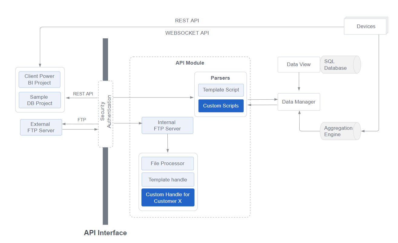
26.1.3 Overview of hosting FootfallCam™ Solution
To host FootfallCam™ Solution on-premise, you are required to prepare 2 server instances for hosting whole FootfallCam™ Solution: -
- Microsoft Windows Server 2016+ (Primary Server)
- Ubuntu Server 20.04 (Secondary Server)
At the highest level, there are 4 major components that forms FootfallCam™ Solution, which is shown in the diagram and table below:
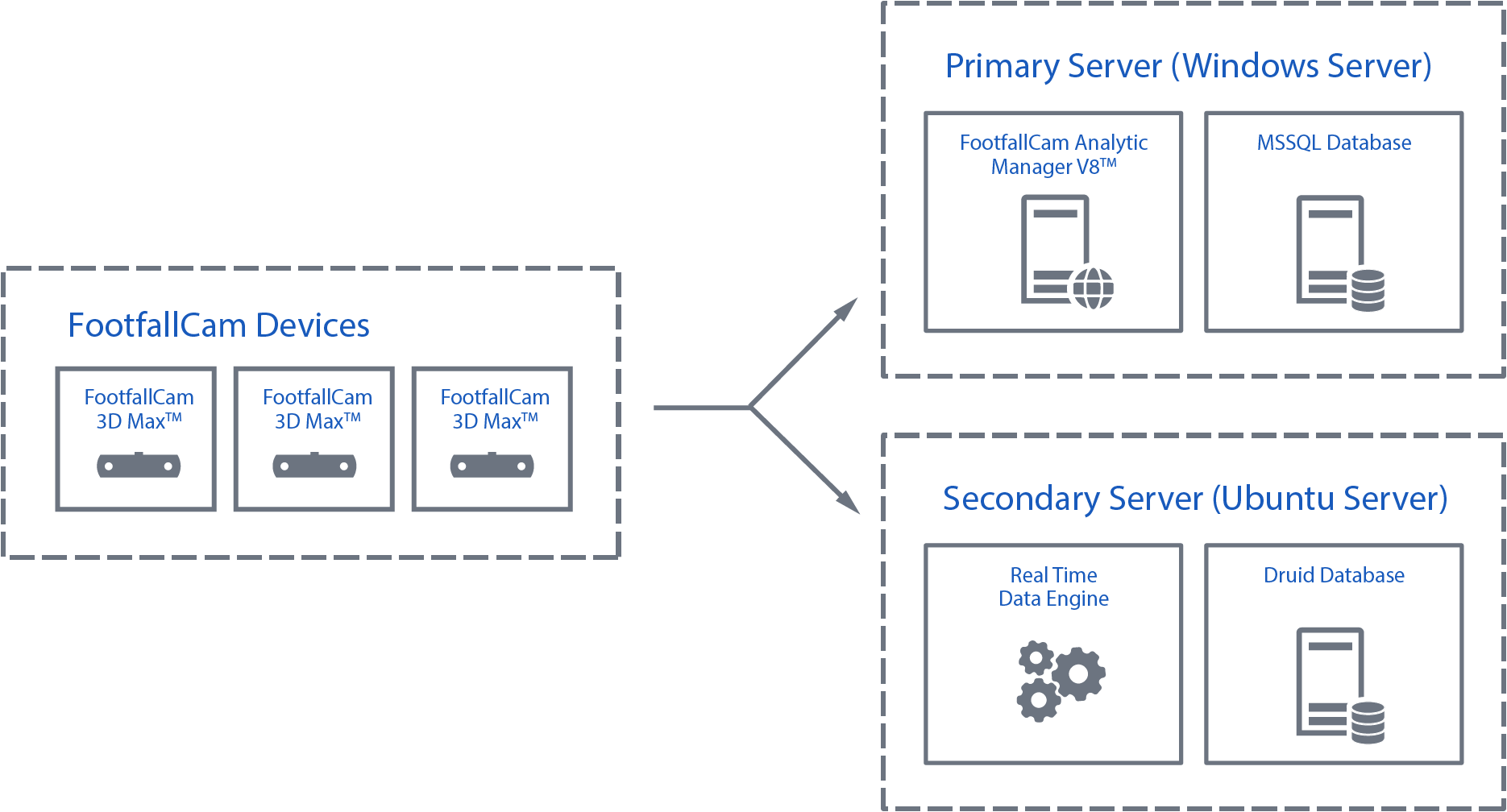
| Component | Description | Compatible OS |
| FootfallCam™ Analytic Manager V9 |
A core web application that allows user to view & generate analytics report, site & device management, and integration in accordance with user's needs into their own system, with addition of user access control, API ready for Import and Export. |
Windows Server |
| Microsoft SQL Database | Stores configuration data, user access data, and log data for FootfallCam™ Analytic Manager V9. | Windows Server |
| Real Time Data Engine |
A collection of services that uses Apache Technologies to communicate, collect, process, and aggregate event-driven data from FootfallCam™ Devices via Websocket protocol, and output information to Druid Database. |
Ubuntu Server |
| Druid Database |
A storage medium for Real Time Data Engine to perform read/write operation with highest efficiency and speed possible. FootfallCam™ also uses this to create an end point that allows FootfallCam™ Analytic Manager V9 to access, manage, and present the data in the dashboard. |
Ubuntu Server |
26.2 Preparing your servers
26.2.1 Choosing the right platform to host FootfallCam™ Solution
There are many cloud providers that can fulfill the requirement on hosting FootfallCam™ Solution, such as Amazon AWS, Microsoft Azure, Google Cloud, OVH Cloud, and many more, depending on the availability in your country or region.
You may also choose to host FootfallCam™ Solution with your own on-premise servers with private network. Be sure to fulfill the network requirements, which you can learn more in Appendix A - Self-hosting Server Deployment Examples.
26.2.2 System Requirements
A correct servers' specification is important to ensure the FootfallCam™ Solution is running reliably and consistently without compromised performance. Table below shows the system requirements for hosting FootfallCam™ Solution, corresponding to the number of FootfallCam™ Devices being supported: -
| Item / Size | Small | Medium | Large |
| FootfallCam™ Devices Count | Up to 100 devices | Up to 500 devices | Up to 2000 devices |
| PRIMARY SERVER | |||
| CPU | 8 Cores 64-bit | 12 Cores 64-bit | 16 Cores 64-bit |
| Memory | 16GB or above | 32GB or above | 128GB or above |
| Storage** | 500GB or above | 1TB or above | 2TB or above |
| Operating System | Windows Server 2016 or above (Standard or Datacenter Edition) | ||
| SQL Server License | Microsoft SQL Server 2016 or above (Standard or Enterprise Edition) | ||
| SECONDARY SERVER | |||
| CPU | 8 Cores 64-bit | 12 Cores 64-bit | 16 Cores 64-bit |
| Memory | 16GB or above | 32GB or above | 128GB or above |
| Storage** | 500GB or above | 1TB or above | 2TB or above |
| Operating System | Ubuntu Server 20.04 LTS or above | ||
26.2.3 Networking Requirements
26.2.3.1 Servers with Public Network
If your servers are hosted in major Cloud Provider such as Amazon AWS, Microsoft Azure, Google Cloud, or OVH, you'll most likely acquire a Public IP Address, which will come in handy in connecting FootfallCam™ Devices to both servers via Internet Connection, as well as providing ease of access for end users to login into the portal.
You are encouraged to acquire a Domain Name from a DNS Provider such as Cloudflare or Fasthosts, and create the following A records shown below: -
| Type | Name** | Target Server | TTL |
| A record | portal.ffc.mydomain.com | <<Primary Server Public IP Address>> | Auto |
| A record | ws.ffc.mydomain.com | <<Secondary Server Public IP Address>> | Auto |
To further secure you servers, you are also encouraged to setup Firewall within your servers or your server provider platform, whichever is available. Be sure to fulfill the Firewall Rules listed in section 26.2.3.3.
FootfallCam will also require to remote access your servers during software installation, maintenance, update, and technical support, you are required to provide remote access for FootfallCam, which you will learn more later in section 26.3.2.
26.2.3.2 Servers in Private Network
If your servers are hosted in your own premises, with private network that is not accessible by public Internet connection, there are several methods to ensure the connectivity between FootfallCam Devices, both of your servers, and to FootfallCam Central Servers are able to establish:
- Setup NAT or Port forwarding to both Primary and Secondary Servers (For devices accessing from external network).
- Implement VPN Solution in every required location (E.g. Fortinet).
Make sure to fulfill the Firewall Rules listed in section 26.2.3.3.
FootfallCam will also require to remote access your servers during software installation, maintenance, update, and technical support, you are required to provide remote access for FootfallCam, which you will learn more later in section 26.3.2.
26.2.3.3 Firewall Rules
To ensure FootfallCam™ Solution is fully functional in on-premise environment, you are required to fulfill configure the following network requirements: -
INBOUND FIREWALL RULES
| Source | Destination | Port and Protocol | Purpose |
| FootfallCam™ Devices, Secondary Server, End User |
Primary Server |
8873 (HTTP) 8874 (HTTPS)** |
|
|
8881 (HTTP) 8882 (HTTPS)** |
|
||
| FootfallCam™ Devices |
Secondary Server |
8080 (WS/WSS**) | Allows FootfallCam™ Device(s) to upload Space Occupancy data to the server. |
| Primary Server | 22 (SSH) | Allows SSH terminal connection for FootfallCam™ Technical Personnel to perform software installation and maintenance when required. | |
| 8081 (HTTP/HTTPS**) | Allows Primary Server to communicate with secondary server for Live-data synchronization to Analytic Manager and configuration update. |
OUTBOUND FIREWALL RULES
|
Source |
Destination |
Port |
Purpose |
|
Primary Server, |
145.239.4.218 |
80 (HTTP) 443 (HTTPS) |
To allow FootfallCam™ Analytic Manager in on-premise servers to communicate with FootfallCam™ Central Servers for the purpose of:
|
|
91.109.10.77 |
To allow FootfallCam™ Analytic Manager in on-premise servers to communicate with FootfallCam™ Central Servers for the purpose of:
|
||
|
51.89.155.156 |
To allow FootfallCam™ Analytic Manager in on-premise servers to communicate with FootfallCam™ Central Servers for the purpose of:
|
If you are going to host FootfallCam™ Solution in a private network, do make sure your firewall rules are able to fulfill the following checklist:
- FootfallCam™ Devices are able to communicate with both Primary and Secondary Servers.
- Communication between Primary and Secondary Servers can be established.
26.3 Installing FootfallCam™ Solution
26.3.1 Server Installation Service
At the moment, FootfallCam™ does not provide any installation files for users to perform installation by themselves due to technical difficulty. Hence, a Server Installation Service can be paid so that FootfallCam™ can perform full software installation, which including:
- Verify servers hardware resources aligned to system requirements.
- Verify servers connectivity aligned to network requirements.
- FootfallCam™ Analytic Manager V9 Installation and Configuration.
- Microsoft SQL Server Installation** and Configuration (License not included).
- Real Time Data Engine Installation and Configuration.
- Druid Database Server Installation and Configuration.
- Continuous software maintenance, update, and support.
You can learn more on requesting Server Installation Service in section 26.1.2 above.
26.3.2 Remote Access Requirements
In the event of software installation, server maintenance or technical issues related to FootfallCam™ devices, hosted software and modules, FootfallCam™ recommends our clients to provide Desktop Remote Access with a fixed access credential (ID and Password), available for 24/7, with given network access.
The reason that we required the Remote Desktop access with fixed credential are as below:
-
The time to perform the necessary work might be different between time zone users and the FootfallCam™ technical personnel, to avoid any delay of action, the unattended access is preferable to expedite the process.
-
To shorten the communication time needed for FootfallCam™ technical personnel with the IT administrator on-site, it's advisable that the password changing is not frequent, except necessary.
You may choose one of the following Remote Desktop Access method below:
|
Remote Access Method |
Instruction / Download Link |
|
Remote Desktop Connection (RDP) |
Click HERE for instruction on how to setup RDP in your Primary Server |
|
TeamViewer 15 |
Click HERE to download and install the application to your Primary Server |
|
AnyDesk |
Click HERE to download and install the application to your Primary Server |
For servers that are hosted in a private network, unless you have chosen a Remote Access Solution such as TeamViewer or AnyDesk, you are required to implement your preferred VPN services, and provide the appropriate access for FootfallCam™ Technical Specialists in favour of server installation and post-installation support.
After completing the above action, please include your credentials into the Server Installation Form before requesting for server installation service.