



3.0 Accessing the Device
3.0.1 Accessing the Device - Setup Wizard Page
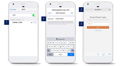
STEP 1 - Connect counter SSID via Wi-Fi and login with password: Please get from FFC support personnel..
STEP 2 - Access to web browser (Safari, Google Chrome) and enter URL: http://192.168.4.1.
STEP 3 - Login with password: Please get from FFC support personnel.
3.0.2 Reset Password - Setup Wizard Page
STEP 1 - Connect counter SSID via Wi-Fi and login with password: Please get from FFC support personnel..
STEP 2 - Access to web browser (Safari, Google Chrome) and enter URL: http://192.168.4.1.
STEP 3 - Click on Change Password and enter your preferred password.
STEP 4 - Complete the process and click on Save.
3.1 Basic Device Details
 |
 |
 |
Counter Info
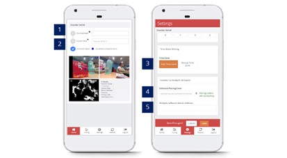 STEP 1 - Access to Setup Wizard page
STEP 2 - Complete the process by entering all the required fields and click on Save.
STEP 3 - Click on Settings tab.
STEP 4 - Complete the process by entering all the required fields and click on Save.
|
Item |
Description |
|
1. Mounting Height |
Enter the measurement from floor to the camera mounting height. |
|
2. Counter Name |
Enter the name of counter location. |
|
3. Time Zone Setting |
Select the time zone. (Info: Time zone selected will be apply to report feature.) |
|
4. Software Pairing Code |
Enter the pairing code. |
|
5. Analytic Software Server Address |
Enter the server address if user is not using the FootfallCam Cloud Portal. |
Time Zone Setting
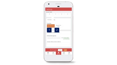
STEP 1 - Access to Device. See 3.0.1 Accessing the device
STEP 2 - Navigate to section Time Zone Setting.
STEP 3 - Complete the process by entering all the required fields and click on Save.
|
Item |
Description |
|
1. Auto Time Zone |
Time zone will be configure same with FootfallCam Analytic Manager server time. |
|
2. Manual Time Zone |
Select the time zone. (Info: Time zone selected will be apply to report feature.) |
3.2 Device Network Setting
3.2.1 Updating corporate network
When users want to change their IP settings on their corporate network, the IP details inputted on the FootfallCam device must be updated as well. If the IP details is not updated on the FootfallCam counter prior to the change of the corporate IP network settings, the counter will not be able to upload visitor counting data to the FootfallCam Analytic Manager.
-
Access to the device. See 3.0.1 Accessing the device
-
Update the IP setting
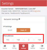
Once the user has access into the FootfallCam device, the user will need to overwrite the existing IP detail with their new setting.
-
The user will need to navigate to the Settings tab on the bottom of the page.
-
Select the option Static IP.
-
Once the user has inputted the new IP settings, click Save to update the settings.
-
When the new IP setting is applied, the FootfallCam device will appear as offline due to unmatched IP setting between the device and the corporate network.
-
-
Update internal network settings
Once the FootfallCam device has been configured for the new IP setting, the FootfallCam will appear as offline and will be unavailable for remote access. The user can then configure their corporate IP settings to match the settings inputted into the FootfallCam device.
3.2.2 Redirecting the server address
When users would like to use a new server for data access from the FootfallCam, the FootfallCam device manager must be logged in onsite to update the new server address. Once the server address is updated, the device must be re-allocated on the new server prior to data display.
- Access to the device. See 3.0.1 Accessing the device
-
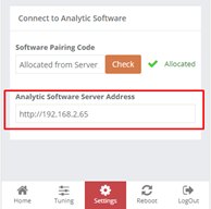
Update the server address - Once the user has access into the FootfallCam device, the user will need to overwrite the existing server address with the new detail.
-
The user will need to navigate to the Settings tab on the bottom of the page.
-
Under the option Connect to Analytic Software, enter the desired address of the new server where data will be streamed to. To use FootfallCam cloud server, please enter www.footfallcounter.com.
-
Once the server address is updated, Reboot the counter.
-
3.3 Device Pairing
In order to pair the devices with the installed site, engineer MUST enter the paring code for the specific site shared by the customer on every devices installed. Otherwise, the data collected by the devices would not able to send to the server for the reporting purpose.
Pairing code is unique for all site(s). Please refer to Section 4.1.1 Share Pairing Code.
3.4 Basic Tuning
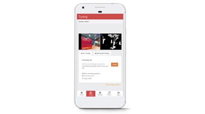
STEP 1 - Access to Setup Wizard page
STEP 2 - Click on Tuning tab.
STEP 3 - Click on Draw in Basic Tuning tab.
STEP 4 - Complete the process by drawing line and click on OK to apply the changes.
3.4.2 Staff Exclusion Kit
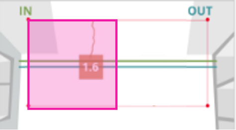
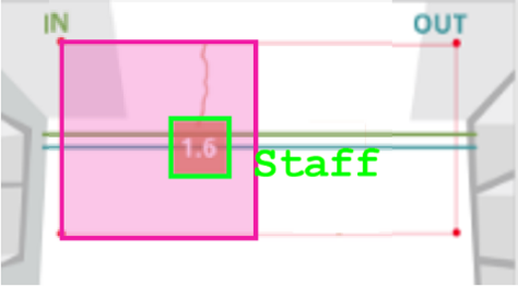
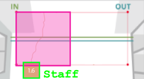
Staff exclusion kit is an additional peripheral attached to the counter internal chipset accompanied by a remote button. User require to press the remote button within the Staff Exclusion Zone for excluding the counting of staff. Two (2) outcomes will be trigger once the remote button is pressed are listed as below:
OUTCOME 1 - LED light on counter will blink 3 (three) times in Red colour and remain in Red colour for 5 seconds to indicate that the staff has been excluded.
OUTCOME 2 - LED light on counter will blink 3 (three) times in Red colour before reverting to original colour.
 |
 |
 |
|
Staff requires to press the remote button within the exclusion zone (pink). |
Staff will automatically be detected as staff. |
Staff can proceed to walk through the entrance as usual. |
|
Option 1 - Automated Setup |
|
STEP 1 - Access to the device. See Section 3.0.1: Accessing the device STEP 2 - Navigate to counter live view and ensure that no individual stand underneath the view of counter. STEP 3 -User may stand underneath the view of counter and press the remote button for 5 seconds. |
|
Option 2 - Manual Setup |
|
STEP 1 - Access to the device. See Section 3.0.1: Accessing the device STEP 2 - Click on Tuning tab and follow by Basic Tuning tab. STEP 3- Click on Draw to indicate a minimum of three (3) points on the live view. STEP 4 - Complete the process by drawing line and click on OK to apply the changes. |
3.5 Walk Test
Initiate a walk test after installing the counter at the site. The walk test varies between 2 minutes to 15 minutes with at least 20 IN and 20 OUT and the time can be adjusted based on your preference.
The purpose of doing the walk test during the installation:
1) This is useful to collect sufficient sample size for faster and better verification.
-all the possible pathways can be tracked from the device
-to speed up the verification process by using the walk test sample (some stores might have a really low
sample from the scheduled video)
2) To ensure all the add-on features can work properly (e.g staff exclusion tags, staff exclusion button)
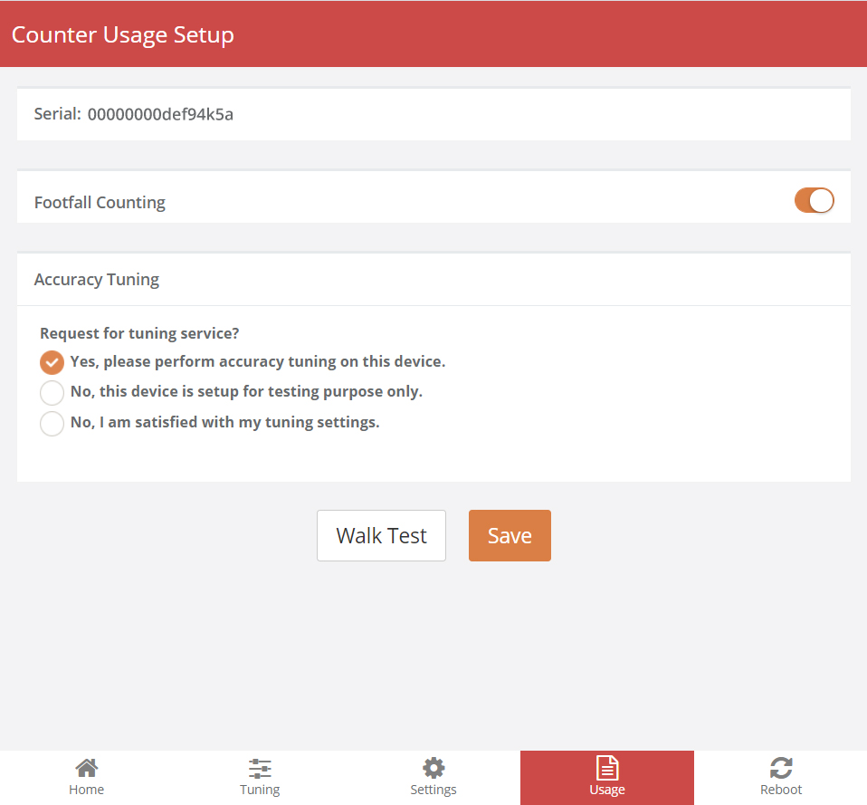
STEP 1 - Navigate to the tab Usage, click on Walk Test to start recording a video.

STEP 2 - After choosing the video duration between 2 minutes to 15 minutes, proceed to click confirm.
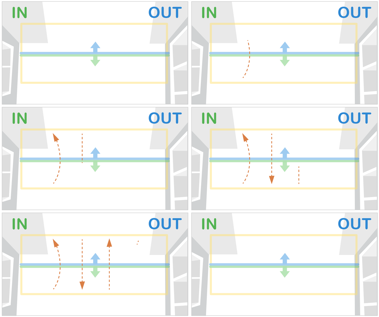
STEP 3 - Walk all possible ways that a normal visitors would enter the premise.
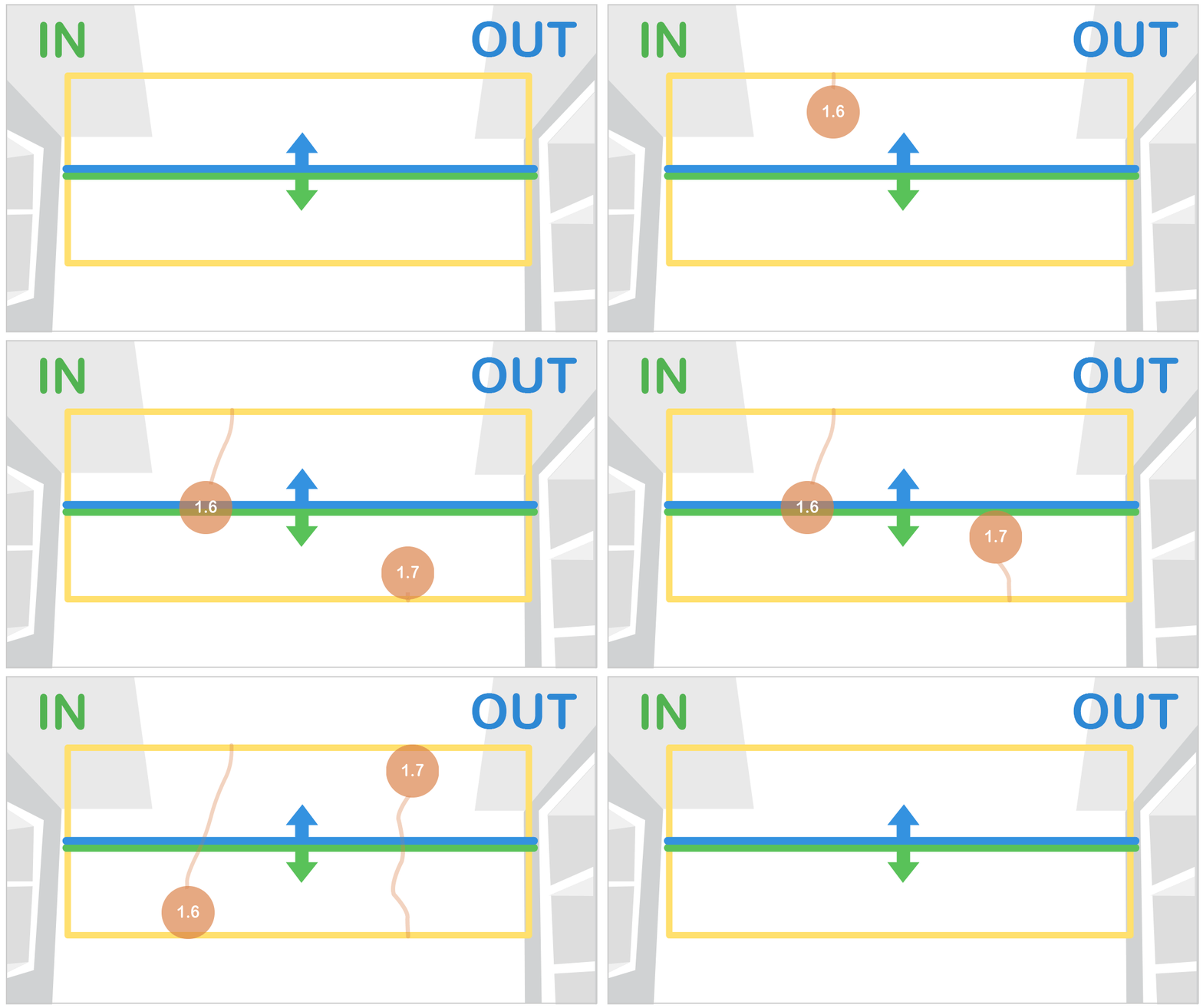
STEP 4 - A head tracker should appear on the person.
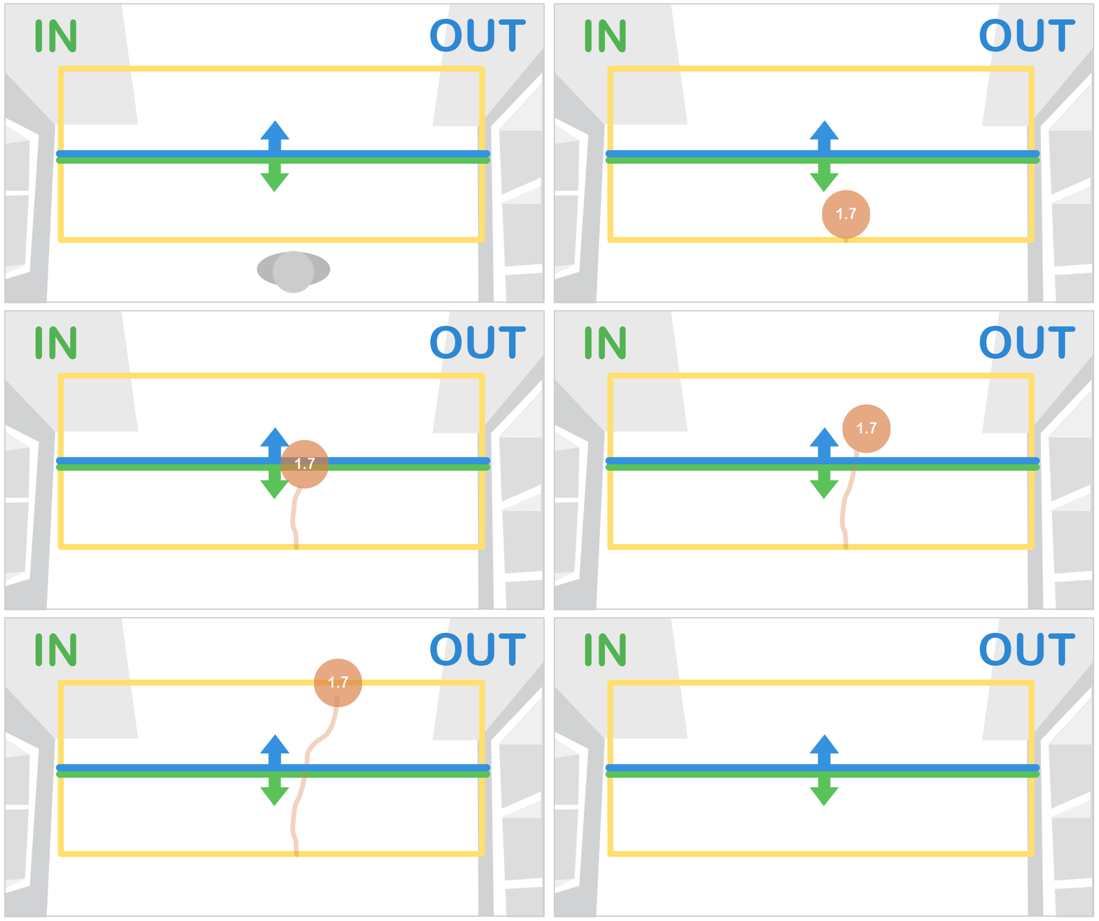
STEP 5 - Counts will be triggered when the person crossed the INOUT lines.
STEP 6 - Once the video has finished recording, there will be a green tick appear to notify. The video is uploaded to server for FootfallCam Specialist to fine tune the settings.
You may also assess the link below for the way to self-record walk test guide:
https://www.youtube.com/watch?v=nRwbYRSTrnY
3.6 Device Control Panel User Guide
Supported Devices: Pro2 (2025), Pro3
Supported Patch Version: v5.2.0_p49 and above
This guide provides instructions on how to access and navigate the Device Control Panel for Pro2 2025, Pro3, and Centroid devices.
Control Panel Interface Overview
Within the control panel, you can access and manage three primary areas:
-
Home Page
Your central dashboard for a quick device overview.-
Camera Streams: View all available live camera streams on your device.
-
Connection Status: Monitor your current device-to-server connection.
-
-
Camera Configuration Page
Your hub for managing camera stream settings, analytics data and visual overlays.-
Traffic Analytics: View live and historical In/Out counts, and visualize data using live or historical Start/End and Path maps.
-
Tracking Zone & Lines: Add, edit or delete tracking zones and In/Out counting lines.
-
AI Models: Select detection models, toggle specific classifiers and enable/disable people ID displays in the live view.
-
Stream Settings: Edit camera stream names, enable/disable Privacy mode and view the hardware mounting guide.
-
Recording Schedules: Start live recordings or schedule them using Online Sim or Low Traffic Online Sim modes.
-
-
Device Configuration Page
Your dashboard for system-level management, hardware health and network setup.-
Device Health & Details: View the serial number, model, firmware patch version and real-time hardware usage (CPU, RAM, Storage, Temperature). Centroid can also view the processing core details.
-
System Operations: Reboot the device, perform a factory reset or pair the device to an analytics server.
-
Time & Network: Manage time settings and network configurations.
-
Integrations: View and manage available data push and camera bindings.
-
3.6.1 Accessing the Device Control Panel
There are three ways to access the device control panel:
-
Via Device IP: Enter the device's assigned IP address directly into your web browser.
-
Via Device Wi-Fi: Connect your computer or mobile device to the device's local Wi-Fi network, then open a browser and navigate to 192.168.4.1.
-
Via Remote Access: Enable and launch remote access directly through the V9 platform.
Method 1: Device IP
-
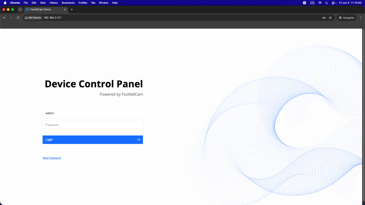
Enter the device's assigned IP address to the browser.

-
You should be redirected to the Login page.
Method 2: Device Wi-Fi
-
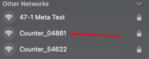
Open the Wi-Fi settings on your PC or mobile device and scan for available networks. Select the network named Counter_XXXXX (where XXXXX represents the last 5 digits of your device's serial number).
-
Enter the following IP 192.168.4.1 into the web browser and you should be redirected to the Login page. (This step is similar to Method 1 above)
Note: The default device login password and device SSID password can be found in the V9 Portal.
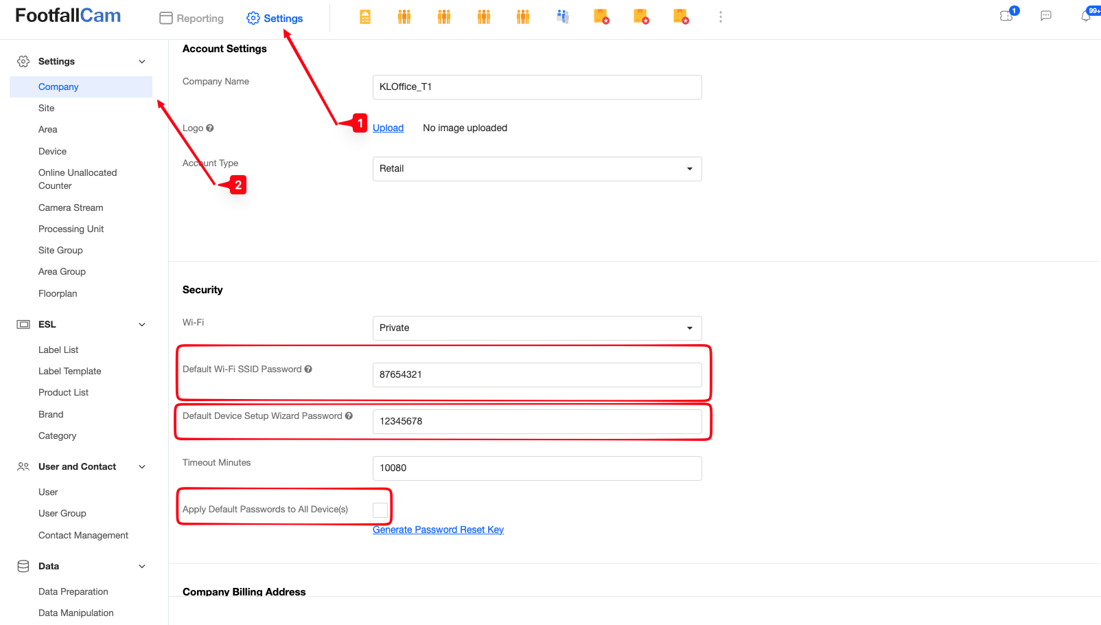
Method 3: V9 Portal
-
Login to your V9 Account and click on the Settings button.

-
Click on the Device Settings button to view all paired devices.

-
Search for your device by entering the serial in the search bar.

-
Once you found your device, click on the Edit button to view device management settings.
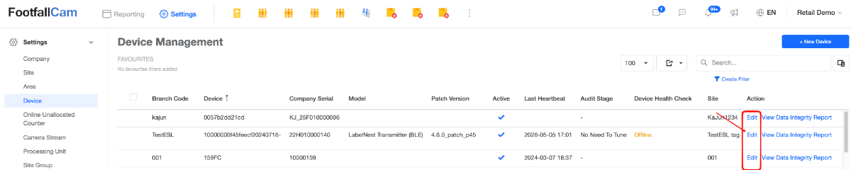
-
In the Device Info view, click on the Settings button to view Device Settings.

-
Once in the Settings section, scroll down until you see the Remote Access toggle and enable it to access the Device Control Panel Login page.
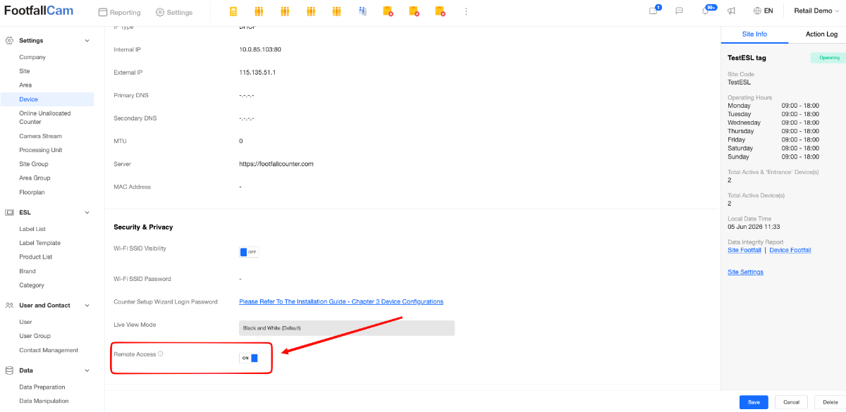
Note: You might encounter a popup after remote access is initiated. Please follow the popup instructions to proceed with the remote access.
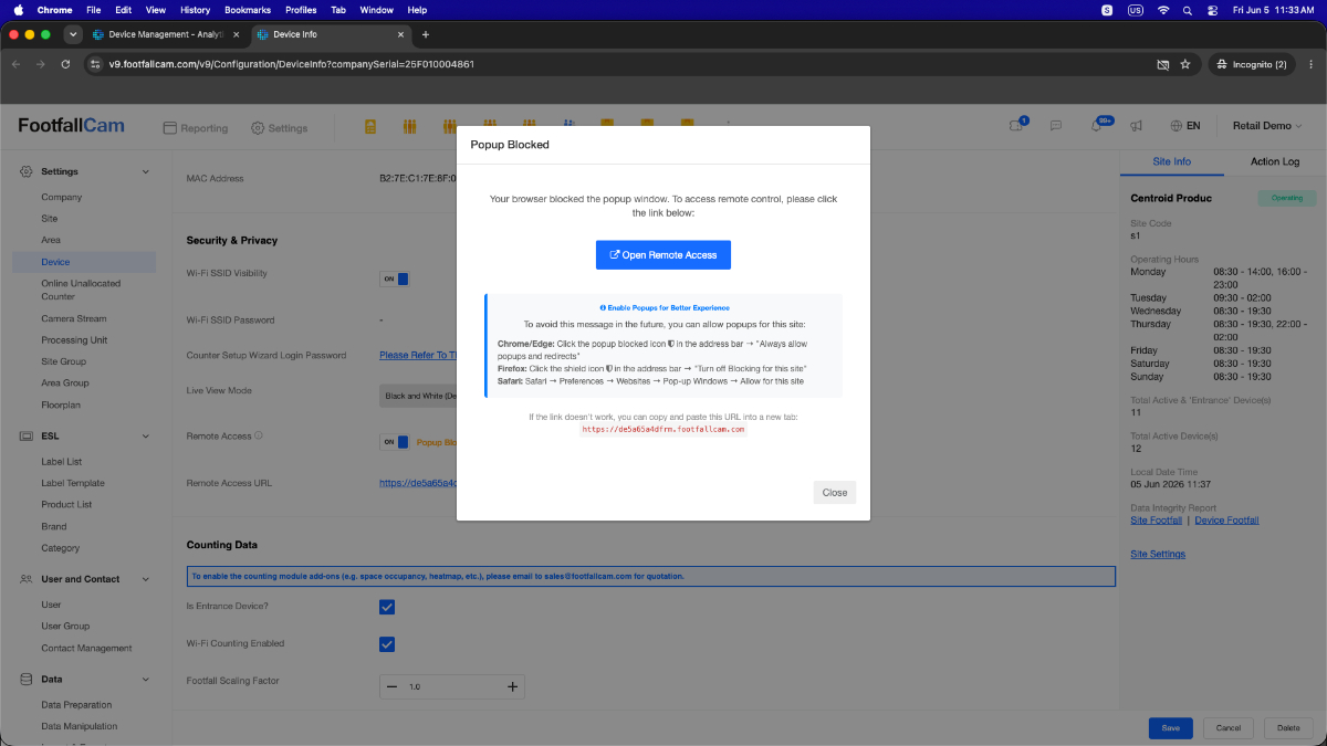
3.6.2 Login Page
After navigating to the login page, enter your credentials to gain access to the main Device Control Panel interface.
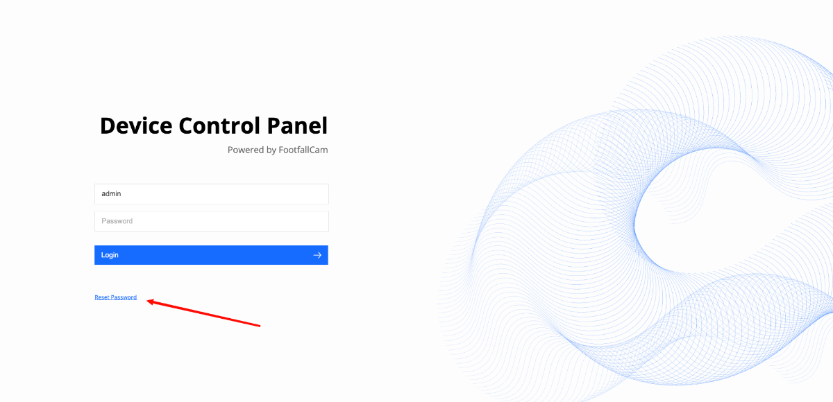
If you forget your password, you can use the password reset option on the screen.
Resetting Your Password
-
Click the Reset Password button to navigate to the password reset page.
-
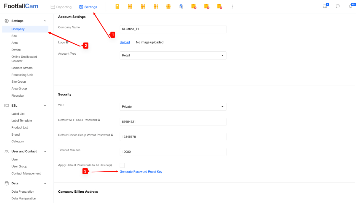
Log into the V9 Portal and navigate to the Key Generator page to generate a password reset key.
-
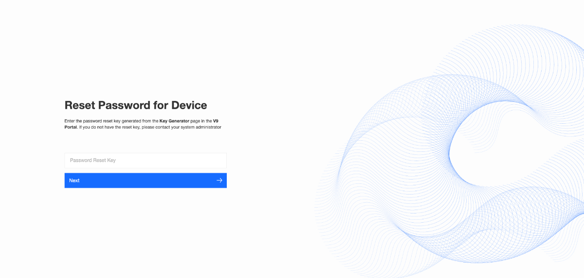
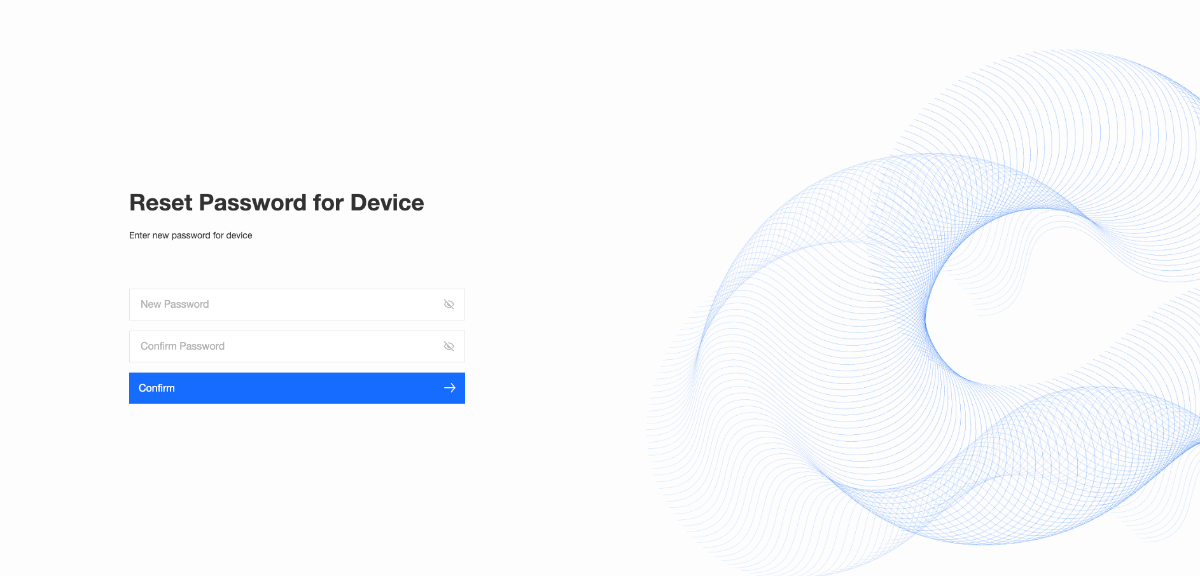
Return to the device reset page, enter the generated Reset Key, and input your new password.
-
Click Confirm to complete the process.
3.6.3 Camera Configuration
The following sections provide detailed guides for managing individual camera streams and configuring their specific analytics settings:
-
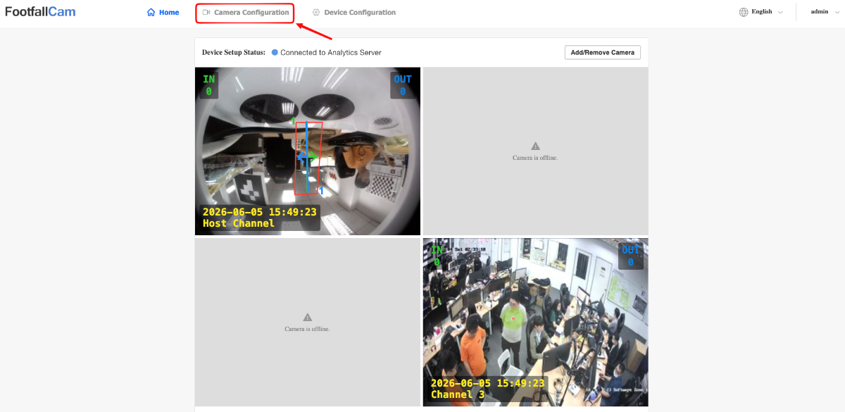
You can access the camera stream settings using one of two methods:
-
Standard Navigation: Click on the Camera Configuration option in the main navigation bar.
-
Quick Shortcut: From the Home Page, click directly on any specific camera stream feed to jump straight to that camera's configuration section.
-
Note:
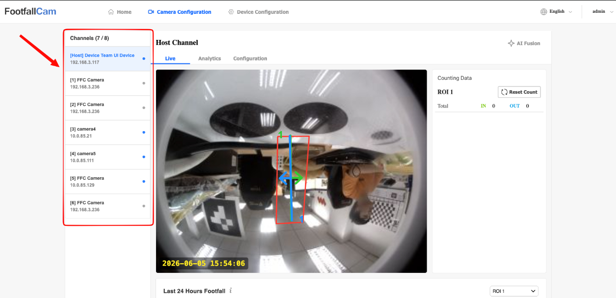
-
For the following Camera Configuration guides, please ensure that you are configuring the right channel / camera stream. You can see the current channel by looking at the left channel side bar.
-
Centroid devices will not have a Host Channel.
-
Currently, IOS devices will not be able to see some of the Live streams. MacOS devices can view the live streams by using any browser except Safari.
Viewing Live Footfall Data
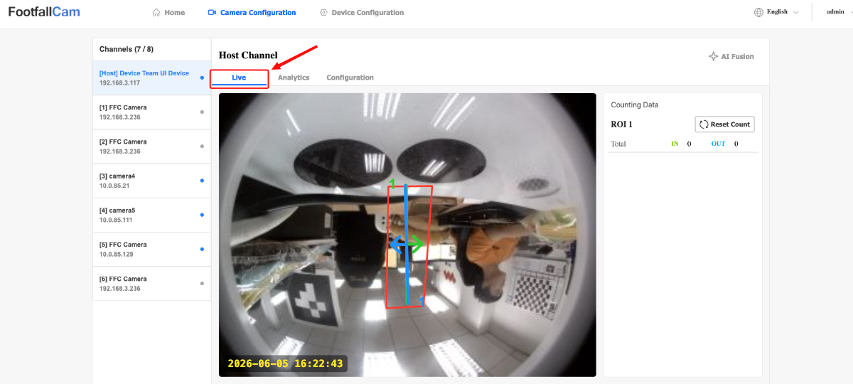
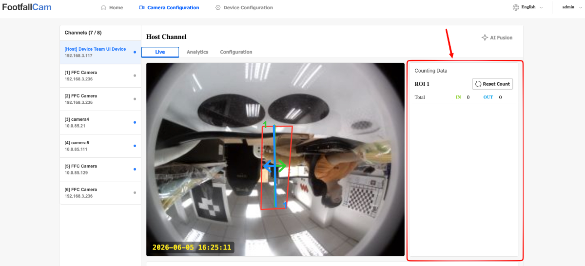
- Click on the Live tab button.
-
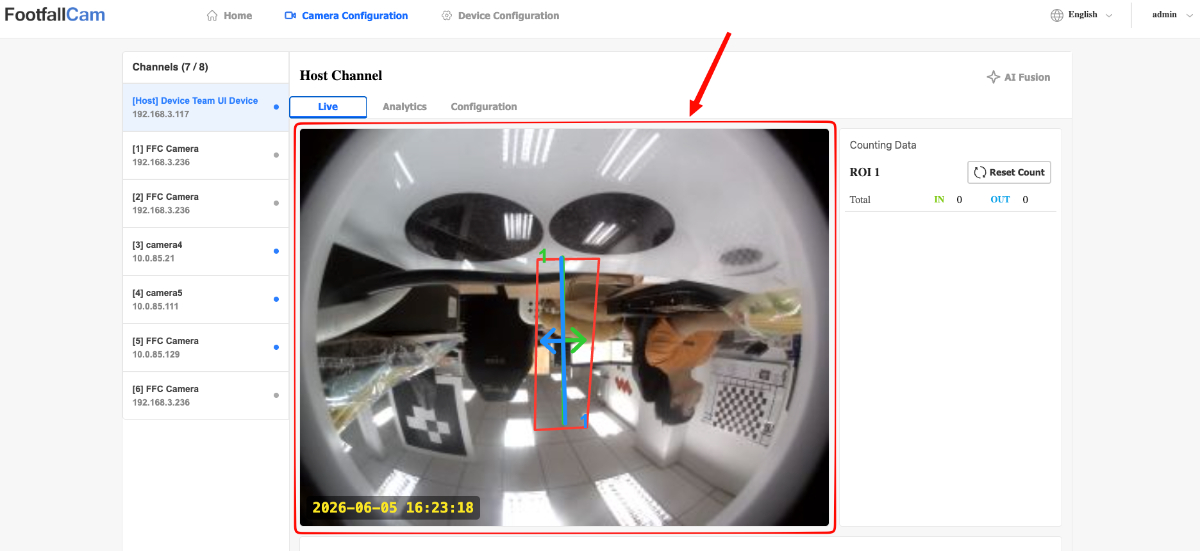
This page displays a live stream that shows live blobs of detected people and current line and zone configurations for the specific channel.
-
The right side bar is a list of tables with live In/Out counts for each ROI (Region of Interest).
-
A graph displaying the last 24 hours of Footfall data is located below the stream and data table.
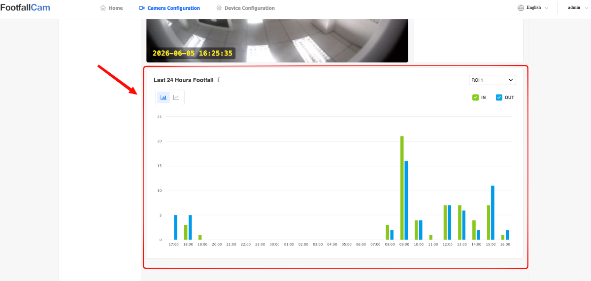
Note:
-
The Live stream will also have HUD indicators to indicate the timestamp, whether the stream is currently recording and whether the stream has Privacy Mode enabled.
-
In Lines and Out Lines are organized by Regions of Interests (ROI) allowing a single camera stream to track In/Out counts of multiple entrances/exits.
-
The Footfall graph can be toggled to be displayed as a bar chart or line graph. Users can also specify which ROI that they want to view data for.
Viewing Historical Footfall Data
-
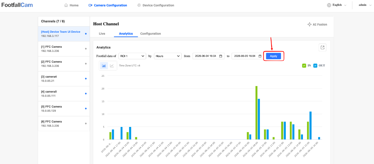
Click on the Analytics tab button.
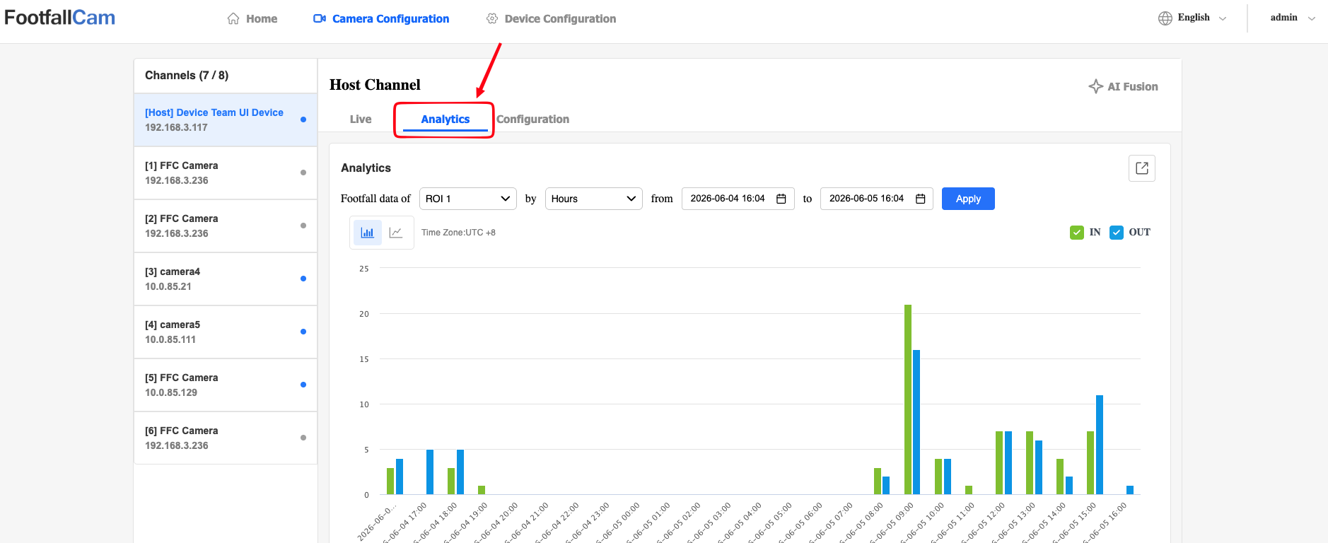
-
Users will be able to view a Footfall data graph similar to the one in the Live tab. However, this graph also includes several configuration options to allow users to view historical footfall data.
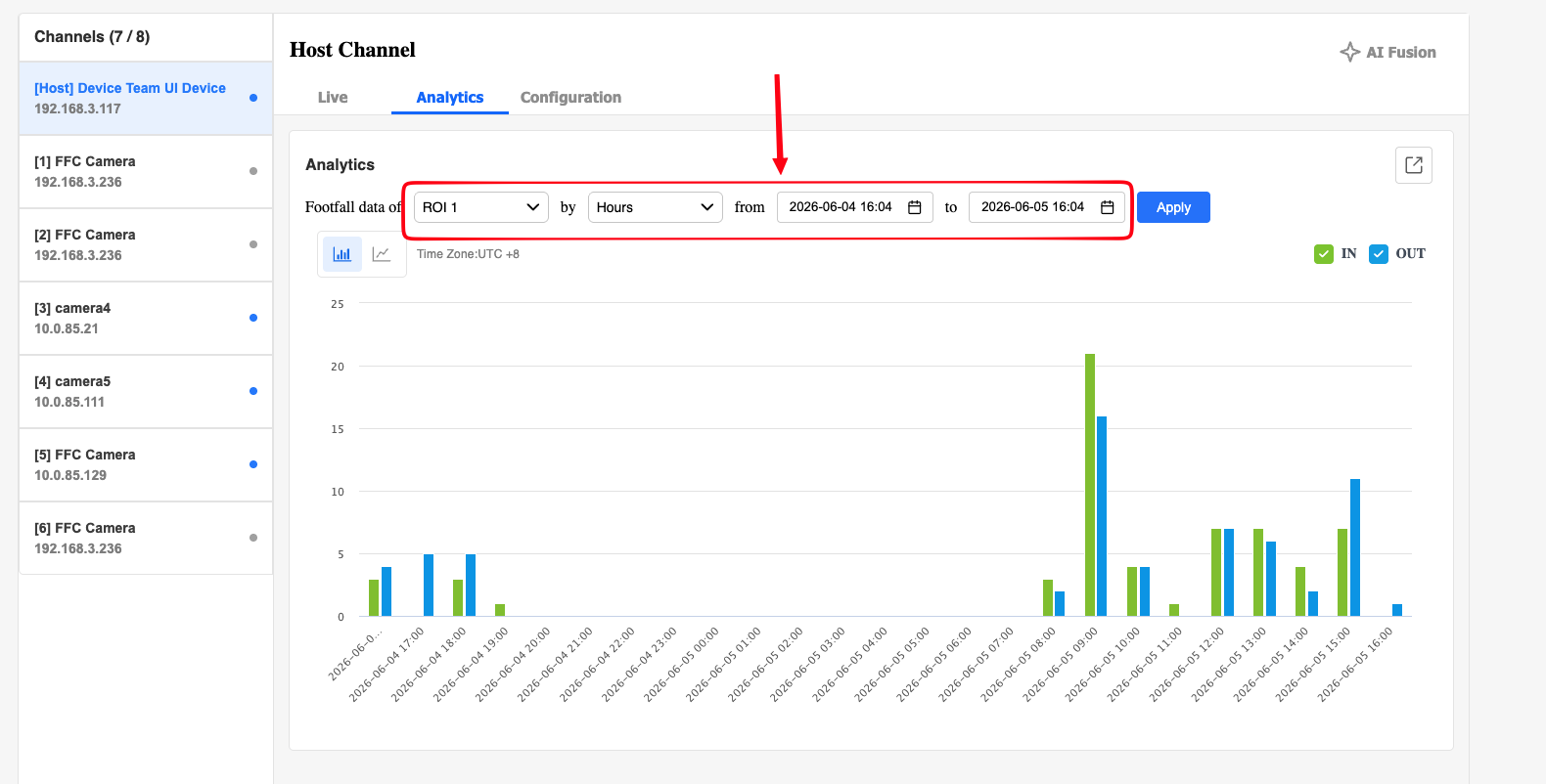
-
Users can configure the following:
-
Region of Interest (ROI) - Users can select any ROI under the current channel.
-
Time Granularity
-
Days
-
Hours
-
Minutes
-
-
Start Date
-
End Date
-
-
Click Apply to apply the settings and view the updated graph.
-
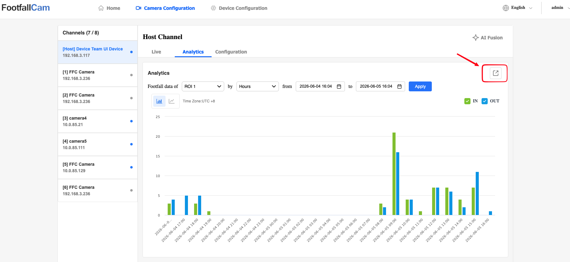
Users can also click the Export button to export the data. Note that this will export the data that is being represented by the current graph to a csv file.
Calibrating Camera Streams
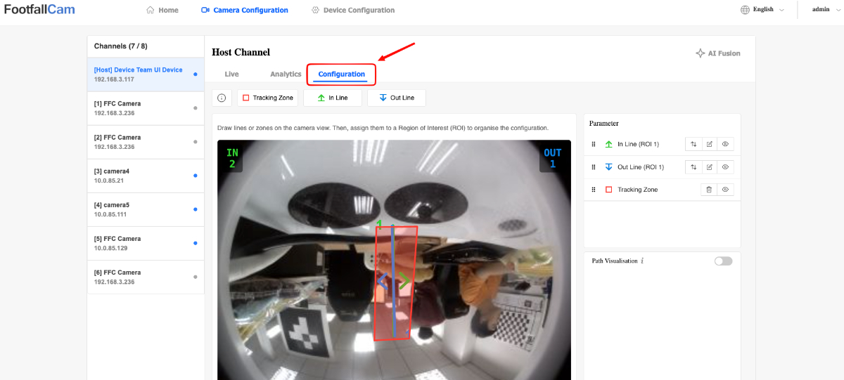
Note that the following subsections will require the user to be in the Configuration section of a camera channel.
-
Click on the Configuration tab button.
Drawing Tracking Zone and Counting Lines
-
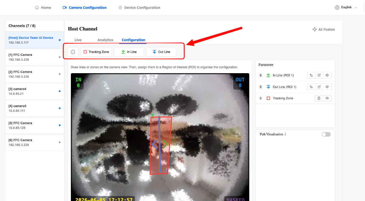
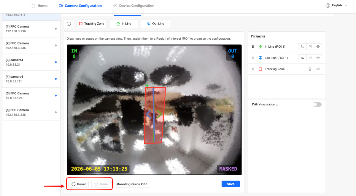
Users will be able to see a list of buttons above the live view which can be used to draw the Tracking Zone and In/Out Lines. There is also a Tooltip button to remind users what each parameter does.
-
There are buttons below the live view to reset all drawings or undo any drawings.
-
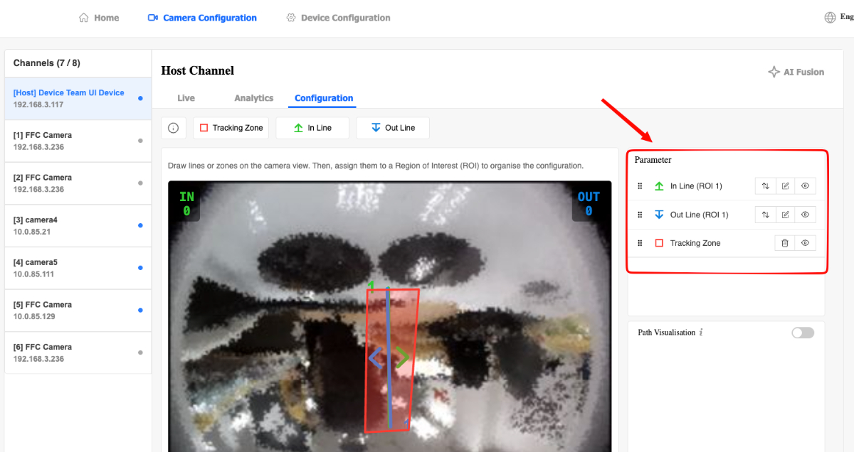
There is a table on the right of the live view to view all currently drawn lines/zones.
-
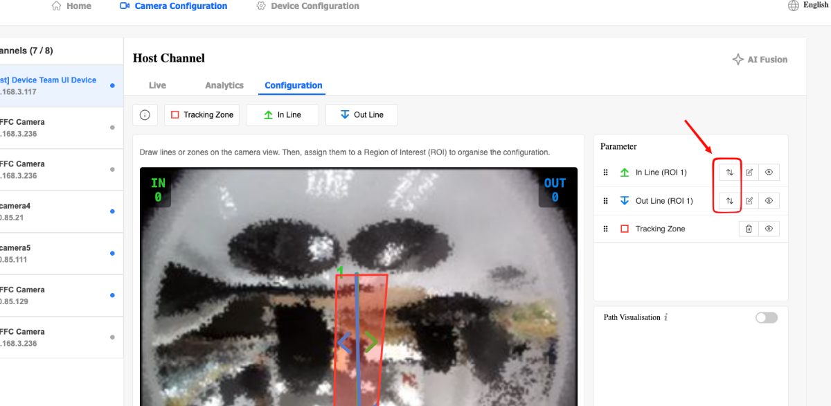
In/Out Lines can have their direction inverted by clicking on the Invert button.
-
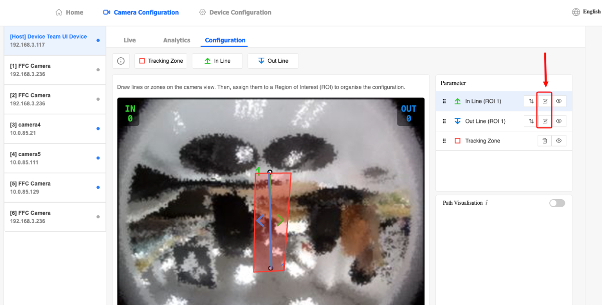
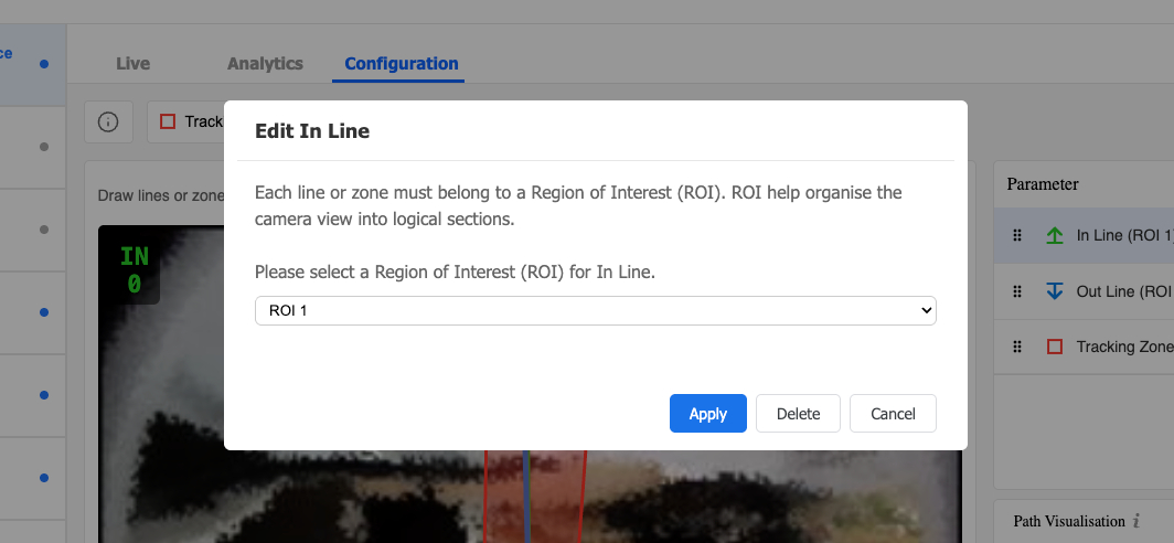
In/Out Lines can have their ROI be reassigned or deleted by clicking on the Edit button.
-
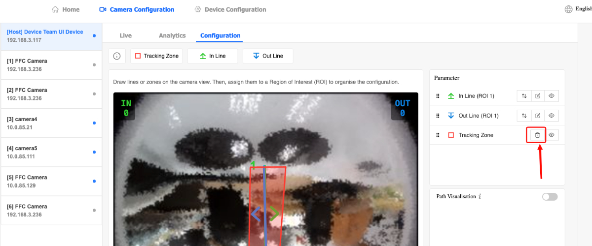
Tracking Zone can be deleted by clicking on the Delete button.
-
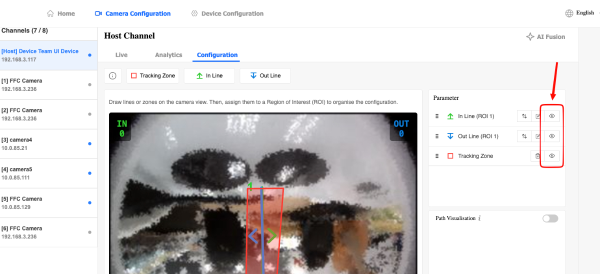
All drawing lines and zones can be temporarily hidden from the live view by clicking on the Hide / Show button.
Note:
-
There can only be 1 Tracking Zone. If no Tracking Zone is present, the device will use the entire live view as the "Tracking Zone".
-
Drawing logic differs based on whether the user is using a PC or Mobile device.
-
PC
-
Click on one of the top buttons to enter Drawing Mode.
-
Click on the live view to start drawing and click again to add more points.
-
Double click to finish drawing.
-
While in Edit Mode, drag a point to move the point and drag the line to move the entire line / zone.
-
Double click a point to remove it and Double click a line to add a new point.
-
-
Mobile Device
-
Tap on one of the top buttons to enter Drawing Mode.
-
Tap on the live view to start drawing and tap again to add more points.
-
Hold tap to finish drawing.
-
While in Edit Mode, drag a point to move the point and drag the line to move the entire line / zone.
-
Hold tap on a point to remove it and hold tap on a line to add a new point.
-
-
Performing Walk Test
-
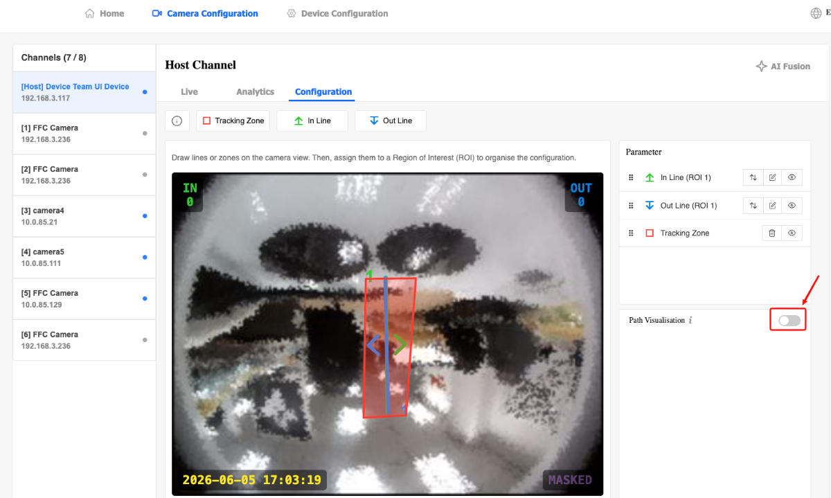
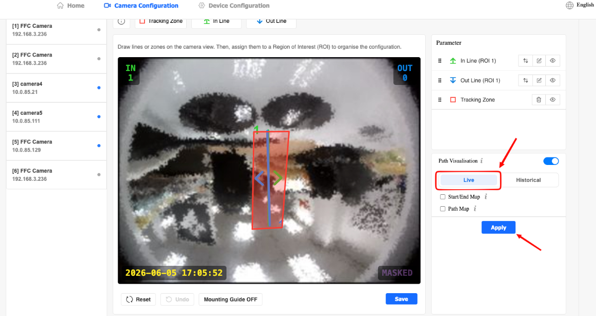
Users can enable the toggle button in the Path Visualisation container to view walk test options.
-
Users can view live start/end maps or path maps by clicking on the Apply button while the Live selector is active. The live path map option is recommended for device installation walk tests.
-
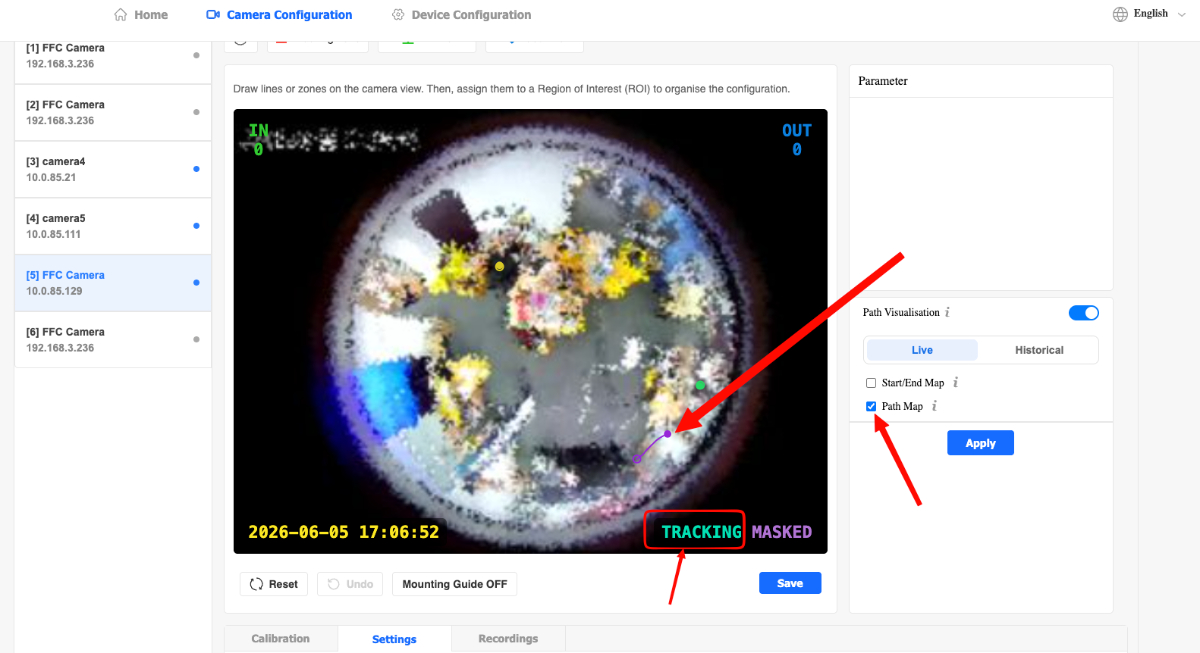
After it has been applied, the stream should show a Tracking status HUD and the user can click on the checkbox to enable their desired visualisation type. (Start/End or Path)
Viewing Historical Path Data
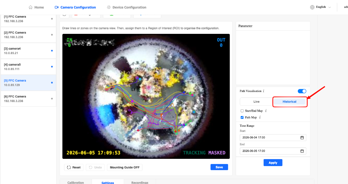
-
Users can also view historical path data as well by clicking on the Historical mode.
-
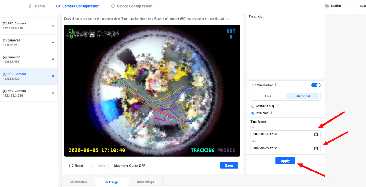
The settings are similar to the Live mode but with the inclusion of a Start Date and End Date selector.
-
Click Apply to generate the historical path data on the liveview.
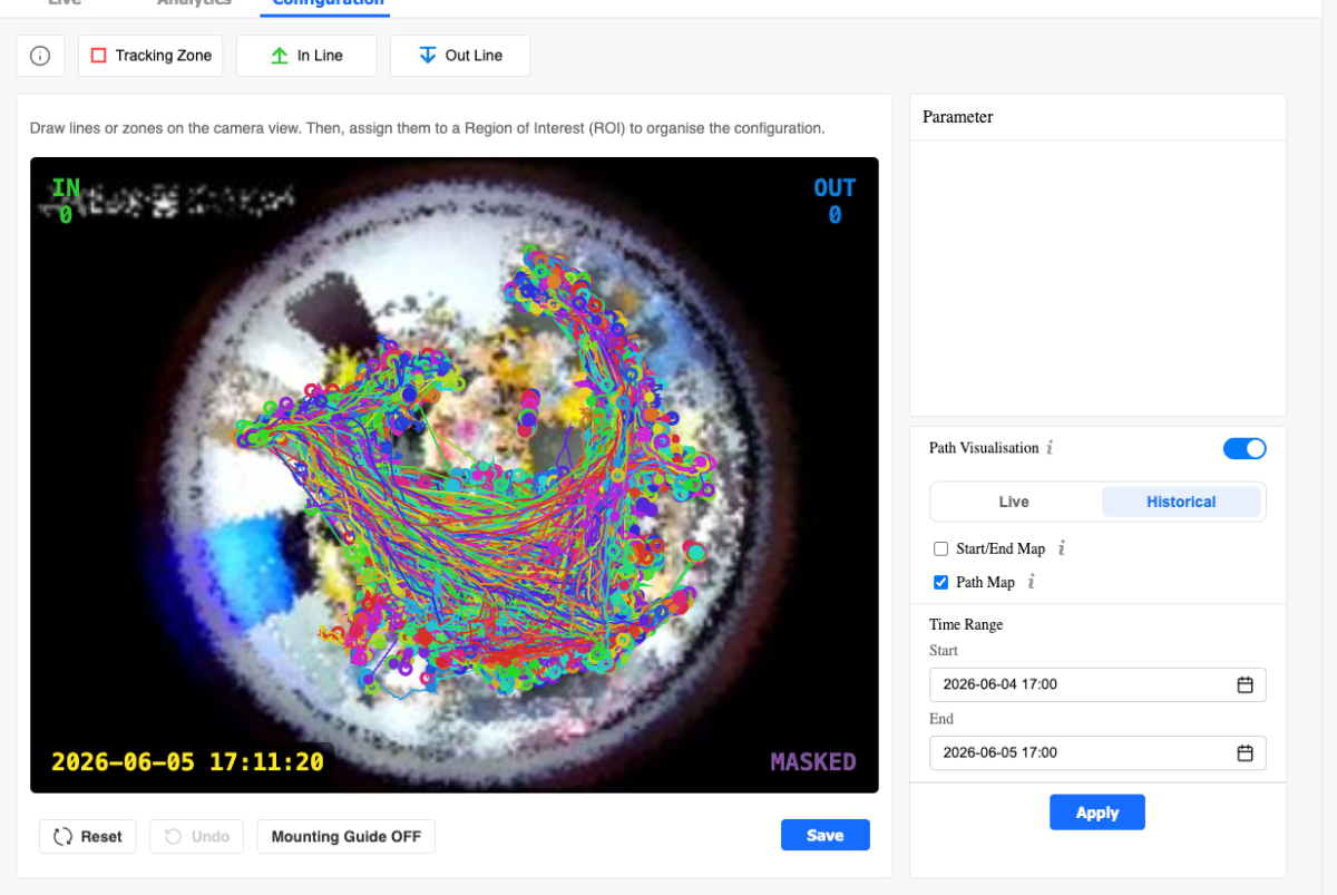
Note: The device only saves historical path data for the past 5 days.
Displaying Device Mounting Guide
-
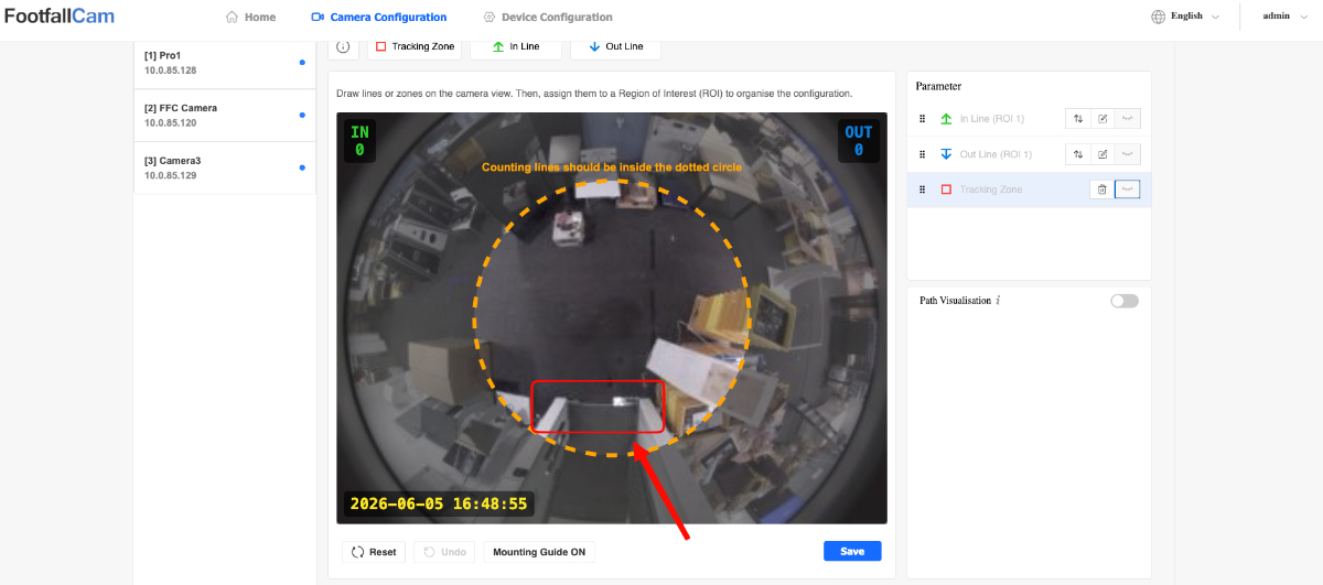
Click on the Mounting Guide OFF/ON button to toggle the Mounting Guide.
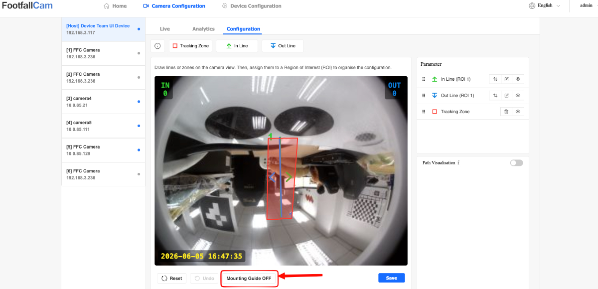
Note: The Mounting Guide is used to determine the optimal mounting position of the device. The base of all entrances being covered by the device must lie WITHIN the Mounting Guide for the most accurate footfall data.
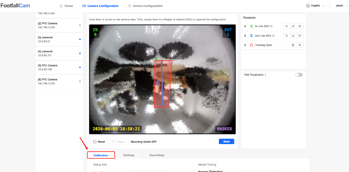
Camera Stream Model Calibration
-
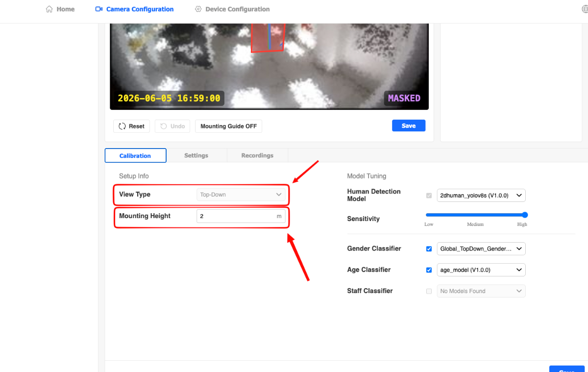
Click on the Calibration tab button.
-
Users can see the current view type of the channel and configure mounting height.
-
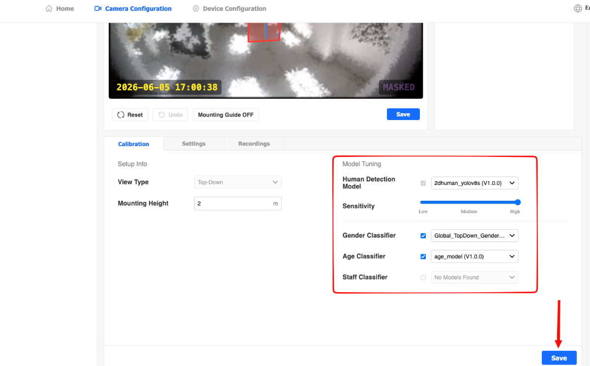
Users can select different Human Detection Models and adjust the detection sensitivity between Low, Medium and High.
-
Users can enable/disable several classifiers such as Gender, Age and Staff.
-
Click Save to apply changes.
Turning On Privacy Mode
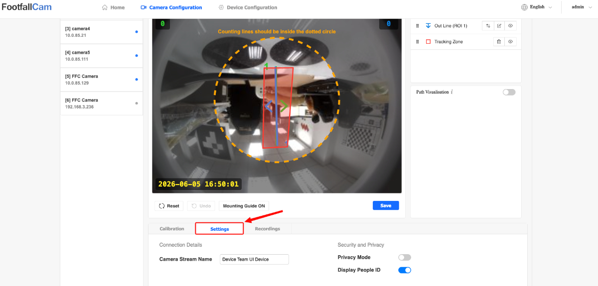
-
Click on the Settings tab button.
-
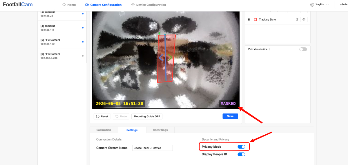
Enable the Privacy Mode toggle to mask the camera stream.
-
Click Save to apply settings.
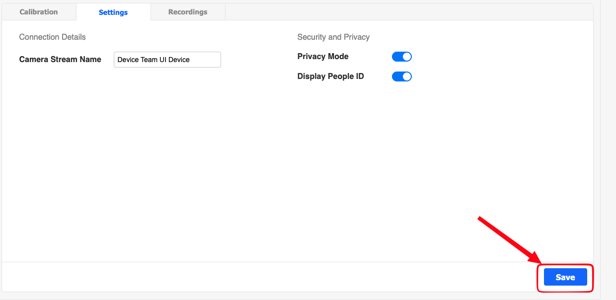
Note: Users can also edit the Camera Stream Name and enable displaying People ID on live blobs here.
3.6.4 Video Recording
-
Click on the Configuration tab button.
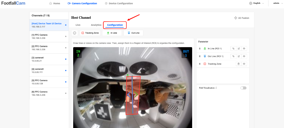
-
Scroll down and click on the Recordings section.
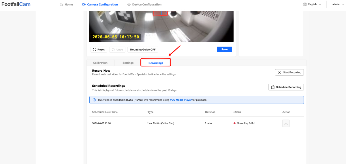
Note:
-
All recorded videos can only be downloaded from the Control Panel when the status is Pending Upload or Uploaded.
-
All recorded videos are automatically uploaded to the analytics server.
-
All recorded videos can be downloaded from the device by clicking on the Download button.
-
VLC Media Player or similar software may be required to view downloaded video recordings as they are encoded in H.265 (HEVC).
Live Recording
-
Click on the Start Recording button to record a live video. Click again to stop recording.
-
The recorded video will be reflected in the table below.
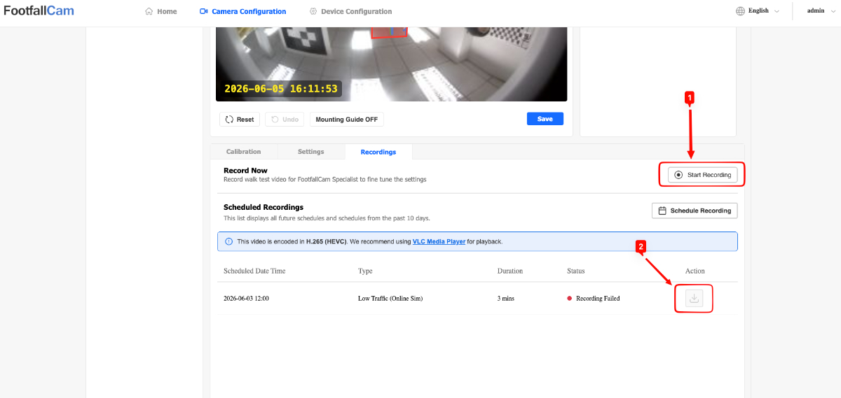
Schedule Recording
-
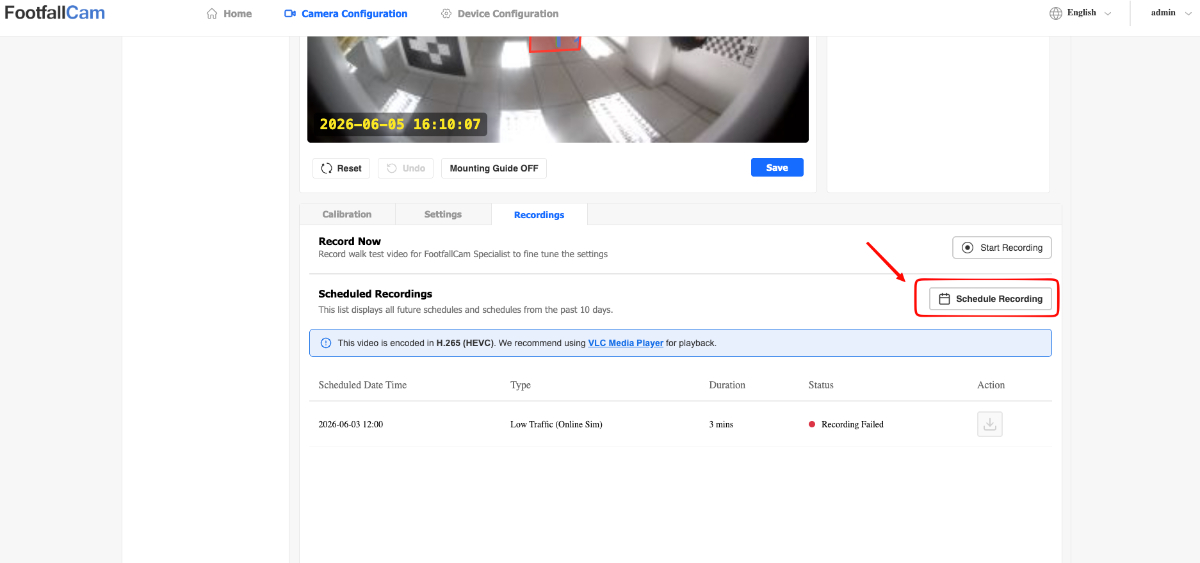
Click on the Schedule Recording button and a popup will appear.
-
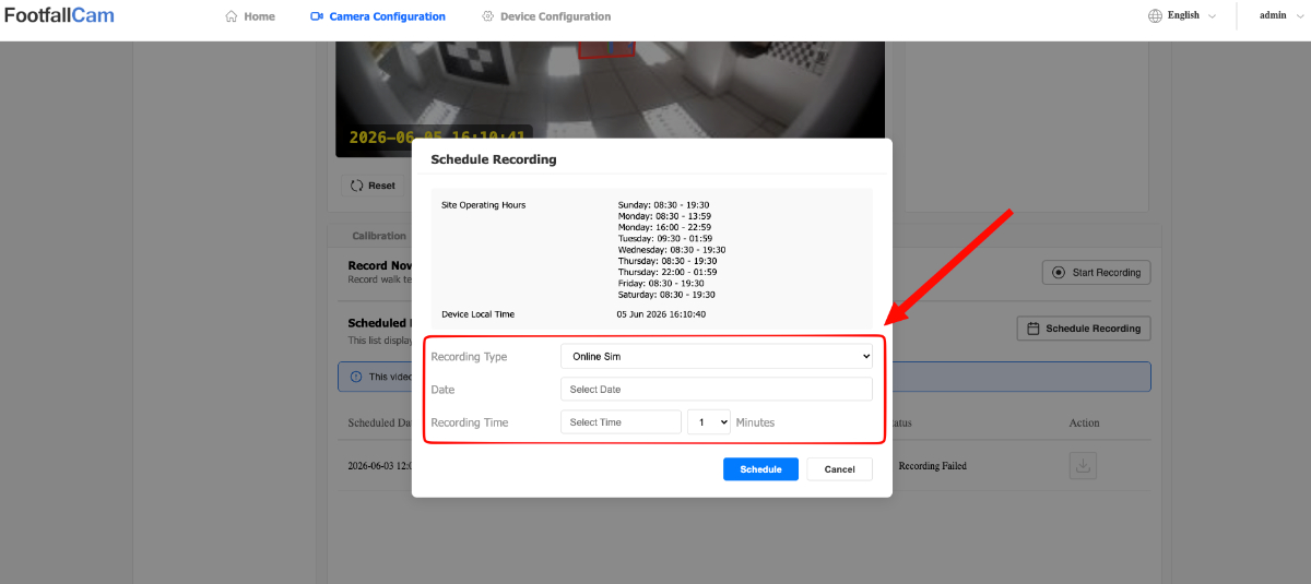
Select desired Recording Type, Date, Recording Time and Duration.
-
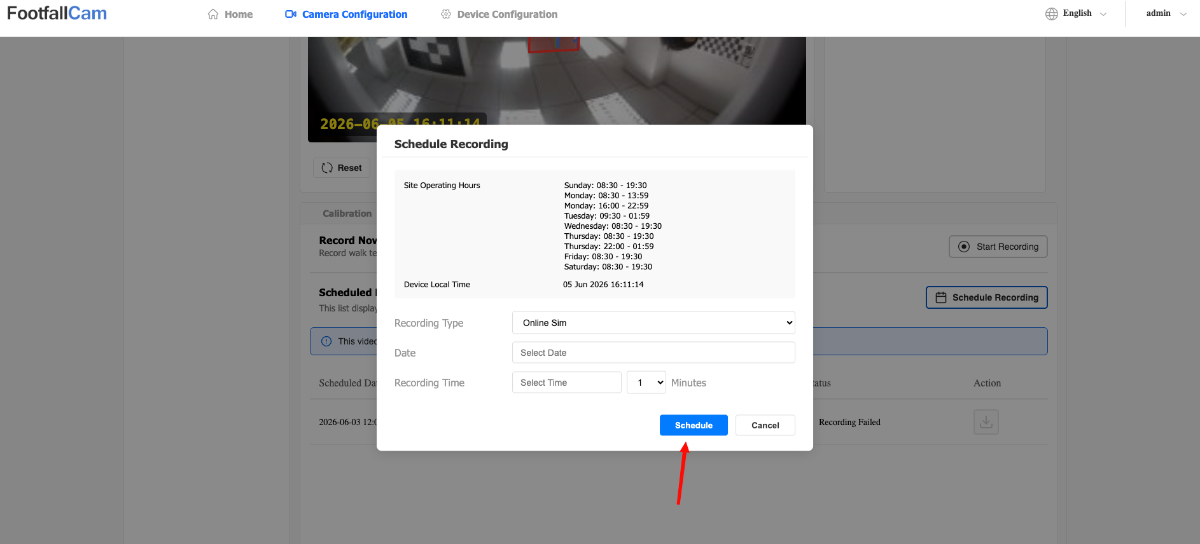
Click the Schedule button to add the scheduled recording.
Note:
-
Online Sim recordings are normal video recordings.
-
Low Traffic (Online Sim) recordings are video recordings that trigger whenever a person is detected in the Tracking Zone. Thus, the final recording is a video that consists of only the times that a person is detected.
3.6.5 Device Configuration
The following sections provide detailed instructions for managing your FootfallCam device. Use these modules to configure system-level operations, network connections, and camera bindings:
Changing Device Control Panel Language
-
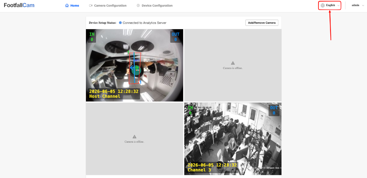
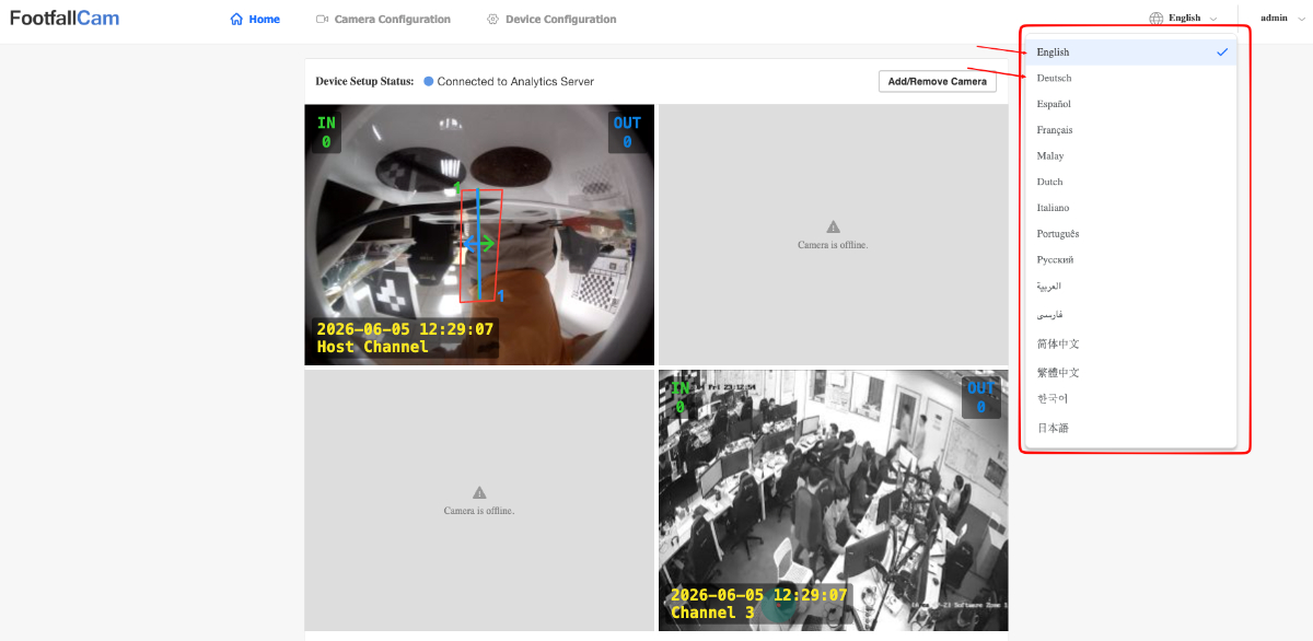
Locate the Language button on the top navigation bar.
-
Click the button to open the language dropdown menu.
-
Select your preferred language from the list to instantly update the interface.
Pairing Device To Analytics Server
-
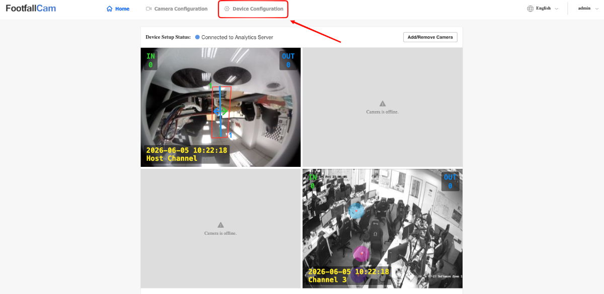
Navigate to the Device Configuration page using the navigation bar.
-
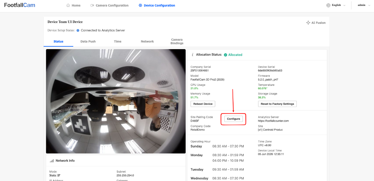
Click on the Configure button next to the Site Pairing Code details.
-
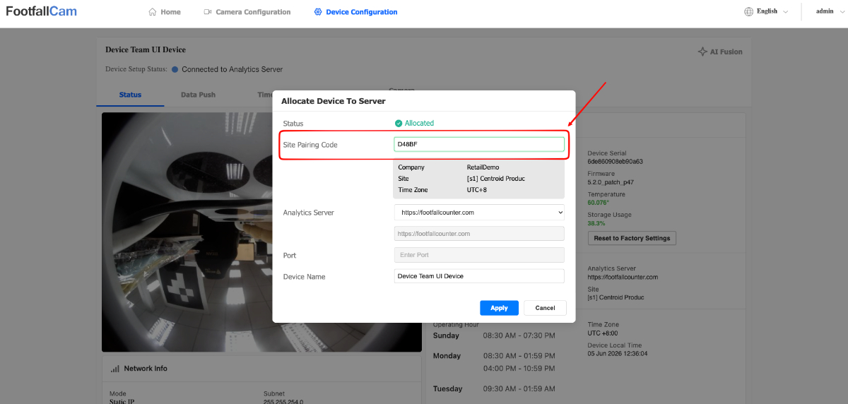
Enter the Site Pairing Code for the Site that you want to pair the device to.
-
Click Apply to proceed with pairing the device.
Updating Device Analytics Server
If you would like to use a new server for data access from FootfallCam, you can also change the server address based on the preconfigured server address list.
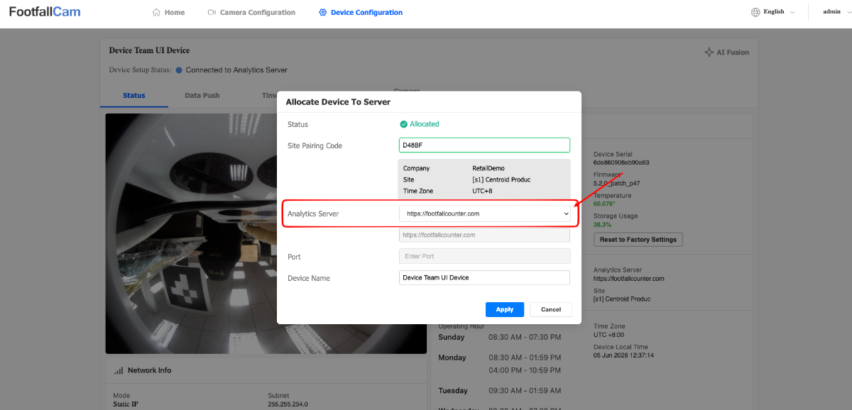
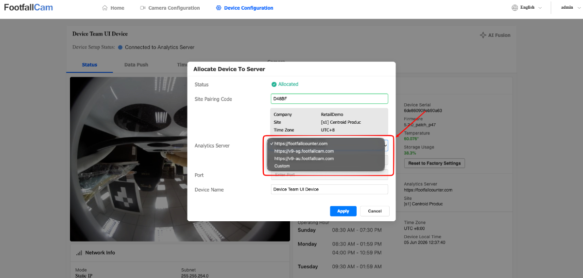
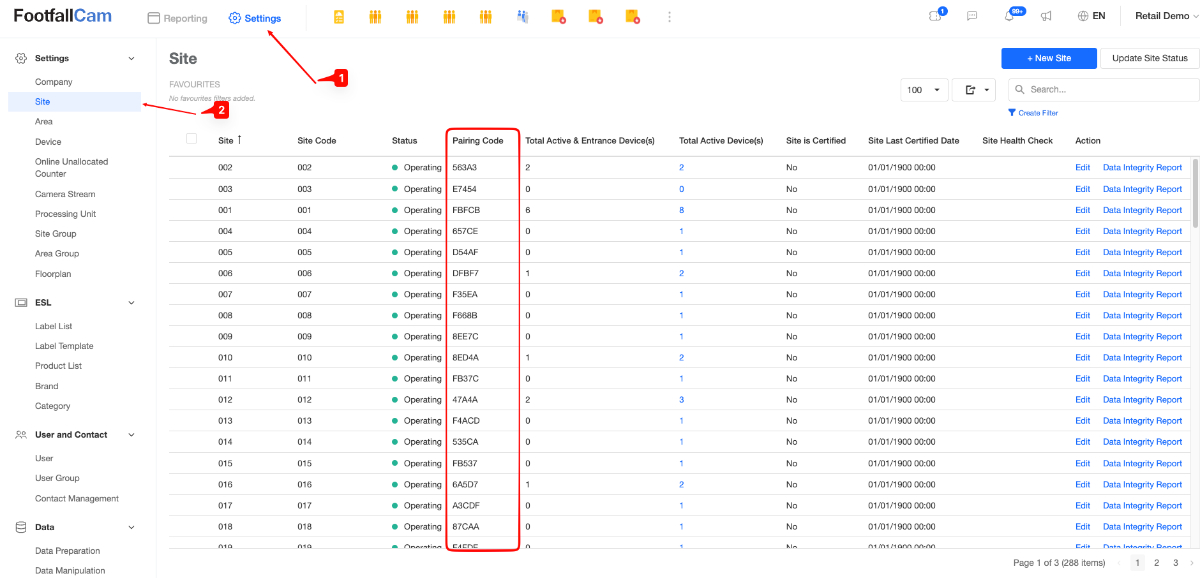
Note: The pairing code is unique for each site and can be obtained from V9 Portal.
Reboot & Factory Reset
-
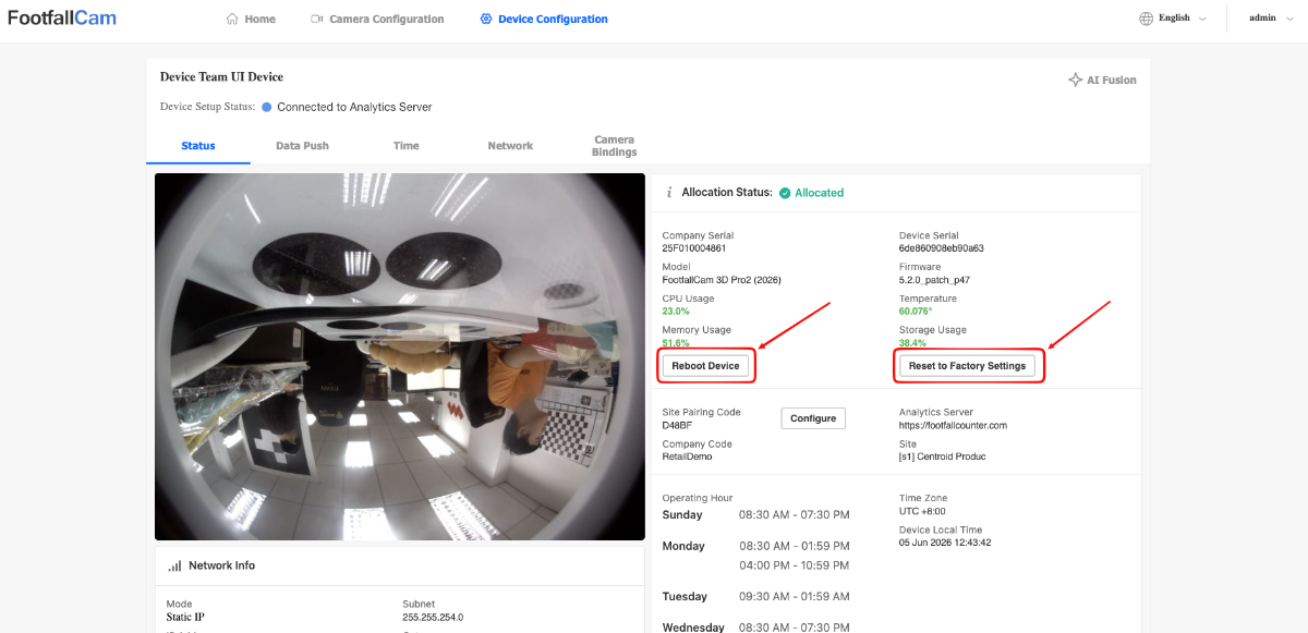
Navigate to the Device Configuration page using the navigation bar.
-
Click on the Reboot button to reboot the device or Reset to Factory Settings button to reset the device.
Setting Up Device for Data Pushing to External Server
-
Navigate to the Device Configuration page using the navigation bar.
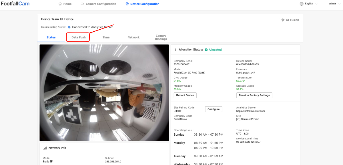
-
Click on the Data Push tab to view Data Push settings.
-
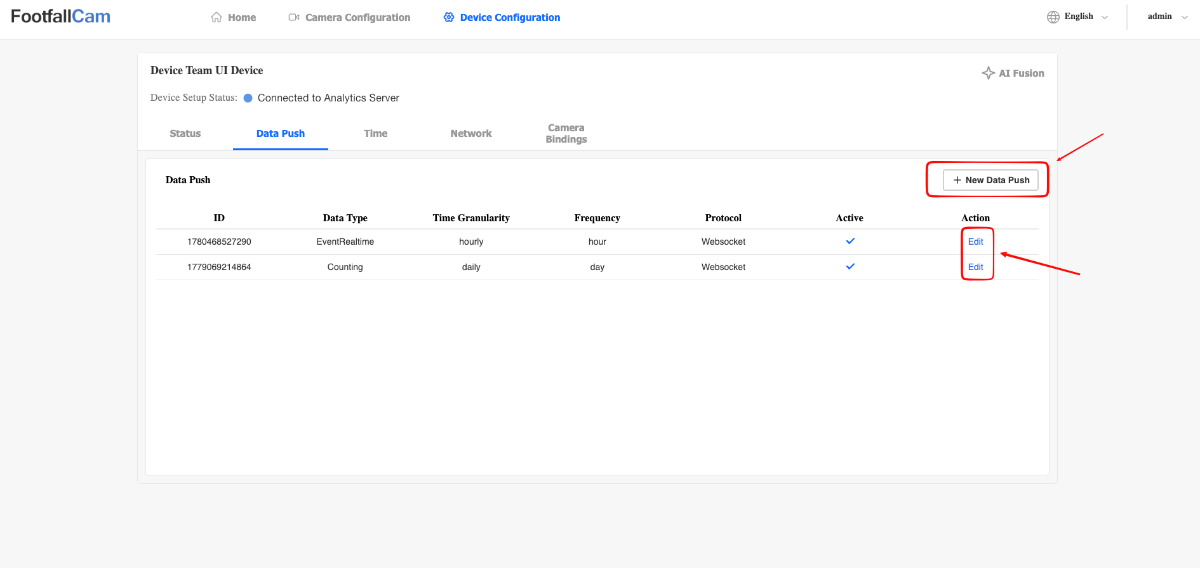
Click on the New Data Push button to add a new data push agent or click on Edit action on a specific data push agent to reconfigure it.
-
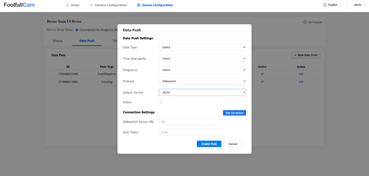
A popup will now appear where you can configure the data push agent.
-
Data Type:
-
In/Out Data - Send In/Out Data at the specified interval.
-
In/Out Event (Real-Time) - Send In/Out Data whenever an In/Out count is detected. Please NOTE that this option will ignore the selected Time Granularity and Frequency options for the data push agent.
-
-
Time Granularity: This will affect how the data push agent aggregates the In/Out data. Currently, the available options are
-
Daily
-
Hourly
-
Every 15 Minutes
-
Minutes
-
-
Frequency: This will affect how often the data push agent sends out the data. Currently, the available options are
-
Daily
-
Hourly
-
Every 15 Minutes
-
Minutes
-
-
Protocol: This will affect how the data push sends the data. Currently, our device only supports Websocket connections.
-
Output Format: This will affect how the data is structured when sent by the data push agent. Currently, our device only supports JSON data structure.
-
Active: This option will determine if the agent is active or inactive.
-
3.6.6 Device Time Settings
-
Navigate to the Device Configuration page using the navigation bar.
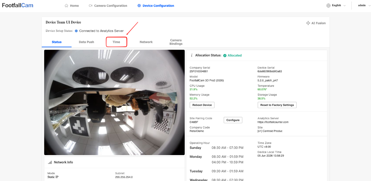
-
Click on the Time tab to view Time settings.
Changing Device Time Zone
-
The user can select their own timezone by enabling the Manual Time Zone toggle and selecting the desired time zone.
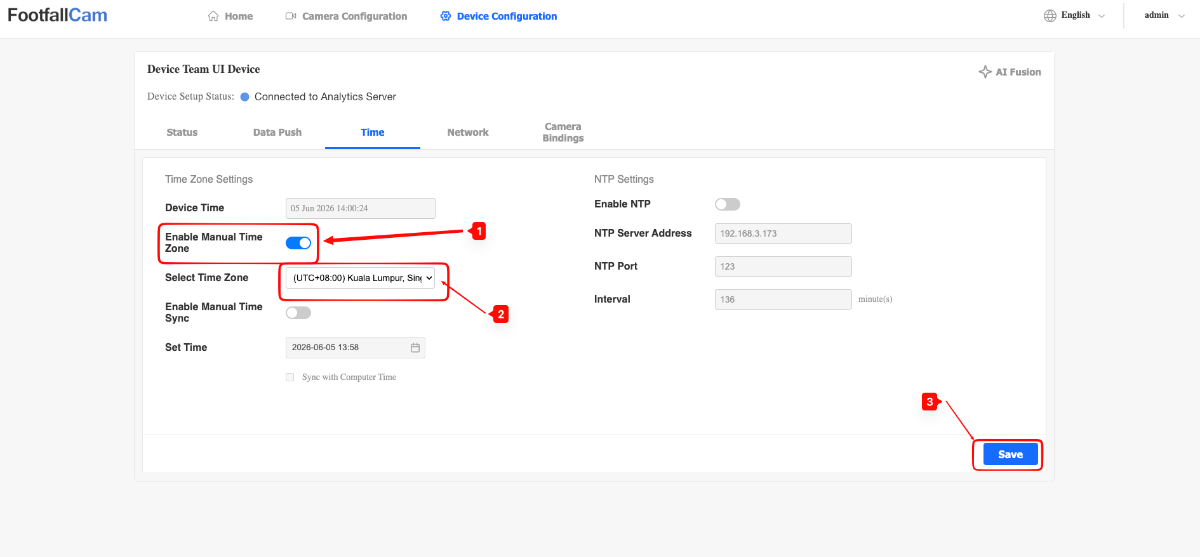
-
Click on the Save button to save your changes.
Note:
- The device will automatically switch to the site's time zone after pairing the device.
Manually Sync Device Time to Desired Time
-
The user can enable Manual Time Sync to set their device time to a specified time or sync with their computer time.
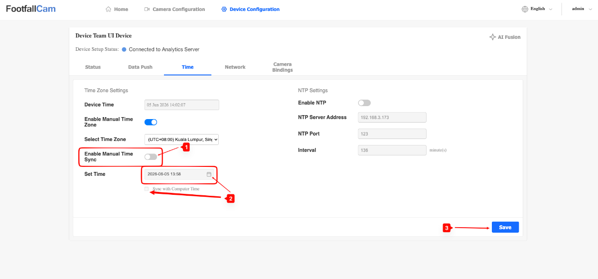
-
Click on the Save button to save your changes.
Note:
-
NTP and Manual Time Sync CANNOT be enabled at the same time.
Configuring NTP server for Device
-
The user can connect the device to a NTP server by enabling the NTP toggle and filling in the NTP server details and sync interval.
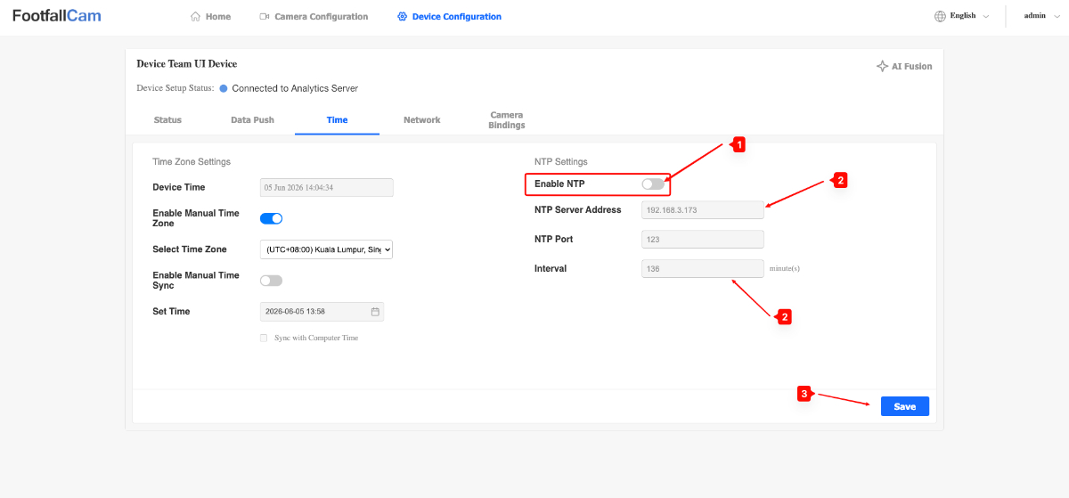
-
Click on the Save button to save your changes.
Note:
-
NTP and Manual Time Sync CANNOT be enabled at the same time.
3.6.7 Device Network Settings
Configure Device to use DHCP or Static IP
-
Navigate to the Device Configuration page using the navigation bar.
-
Click on the Network tab to view Network settings.
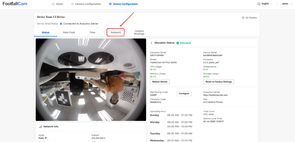
-
Users can configure the device to be DHCP or Static IP in the Network section.
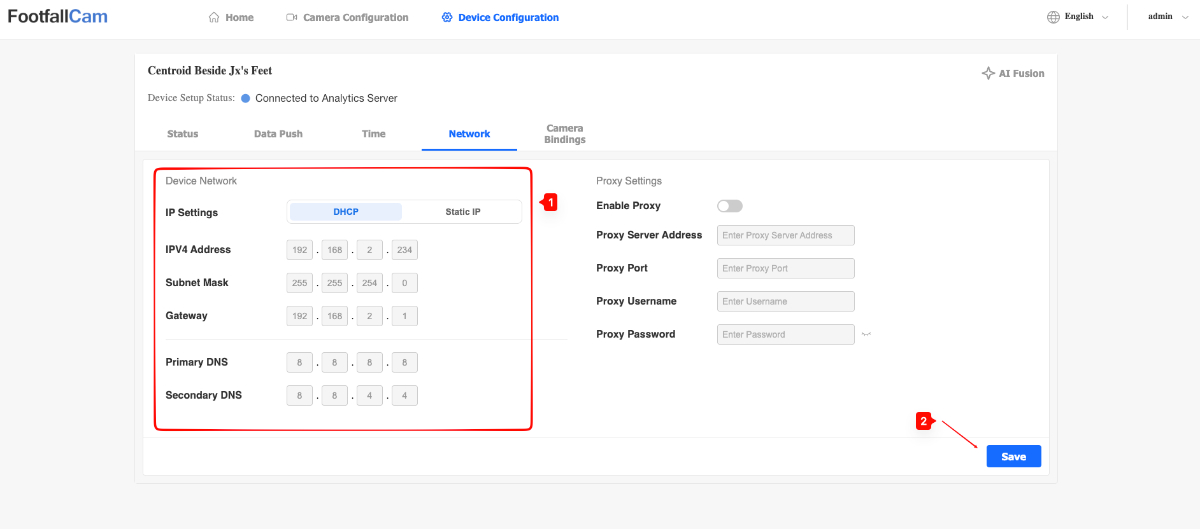
Note:
-
Pro2 (2025) and Pro3 devices always require the user to input the Primary DNS and Secondary DNS when saving any network changes. If a user wants to switch to Static IP, they will also need to input the IPv4 Address, Subnet Mast and Gateway. DHCP only requires the DNS fields to be filled.
-
Centroid devices have a minor difference, their DHCP setting does not require DNS fields to be filled.
Connecting a Device to Proxy Server
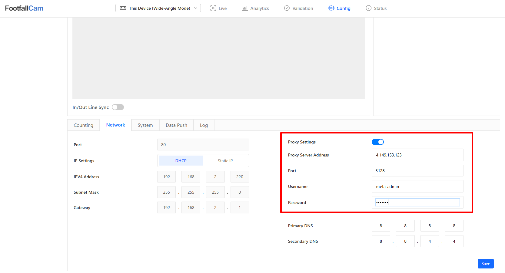
Users can configure the device to connect to a proxy server. They must first enable the proxy toggle and fill up the relevant fields before clicking the Save button.
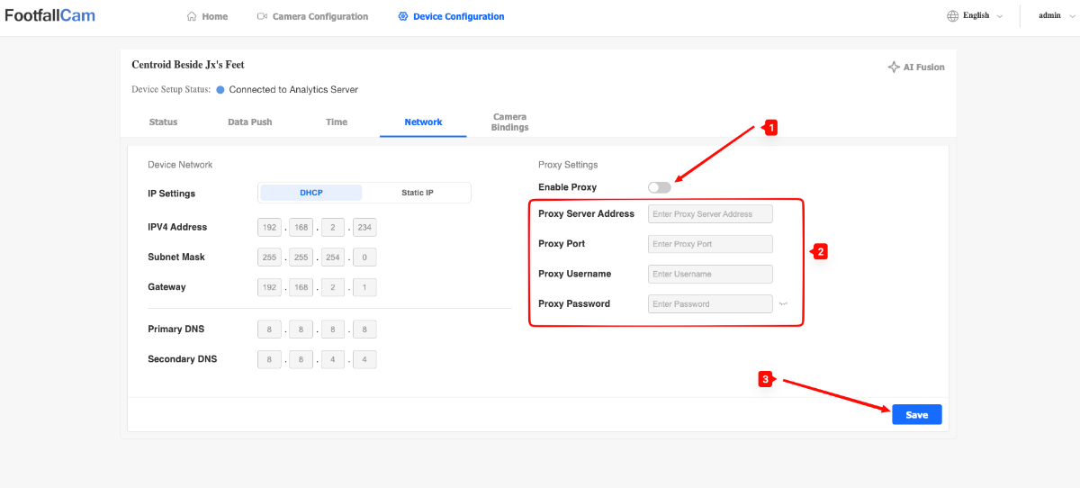
Note:
-
When setting up a proxy server connection, users must specify the proxy server address and port.
-
The proxy username and password is optional. However, if either one is provided, the other must also be provided in order to save the setting.
3.6.8 Camera Bindings Management
There are two ways to navigate to the Camera Bindings configuration section, depending on your current workflow.
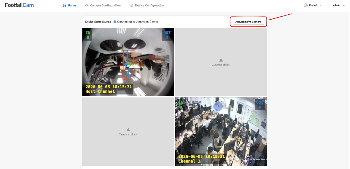
Method 1: Home Page
-
Users can click on the Add/Remove Camera button in the Home page to directly navigate to the Bindings page.
Method 2: Navigation Bar
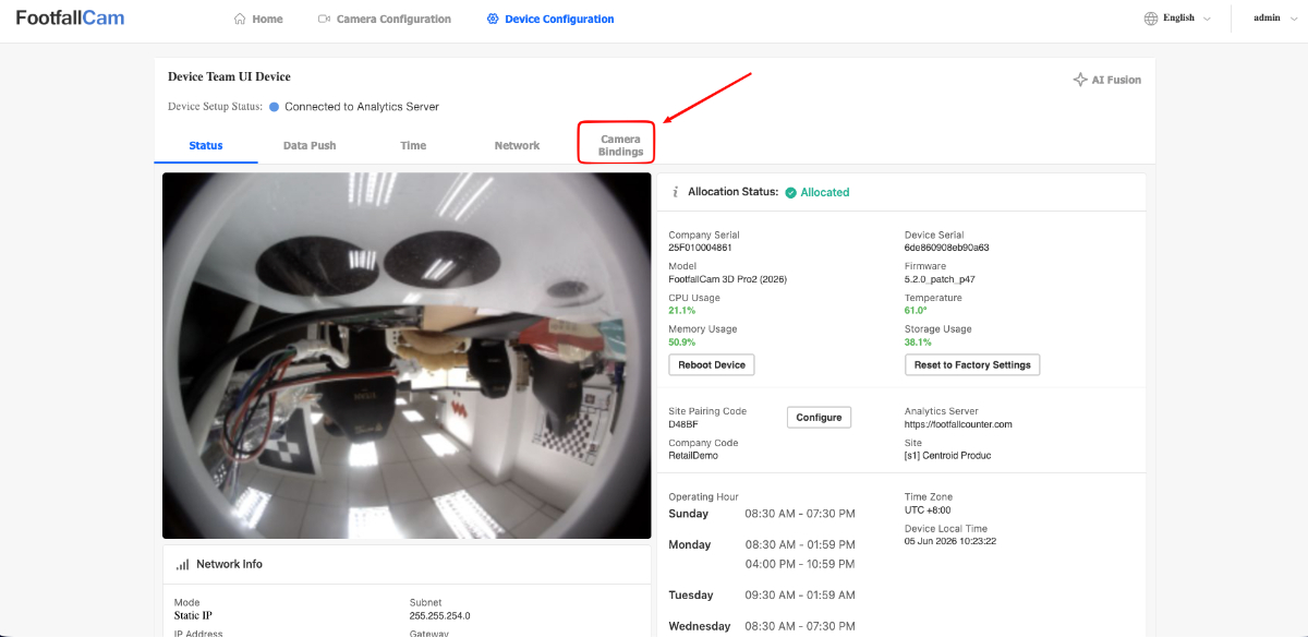
- Users can click on the Device Configuration navigation button in the navbar to navigate to the Device Configuration pages.
-
Once in the Device Configuration page, click on the Camera Bindings tab button to view camera bindings.
Adding Camera Streams
There are currently 2 ways for users to bind new camera streams to the device. The first method is to use the Search Nearby Devices button to discover nearby cameras and the other method is to click on the Add Camera button. The first method is the recommended method as it is more simple and faster.
Method 1: Search Nearby Devices
-
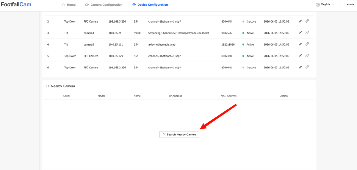
In the Camera Bindings section, scroll down and click on the Search Nearby Camera button.
-
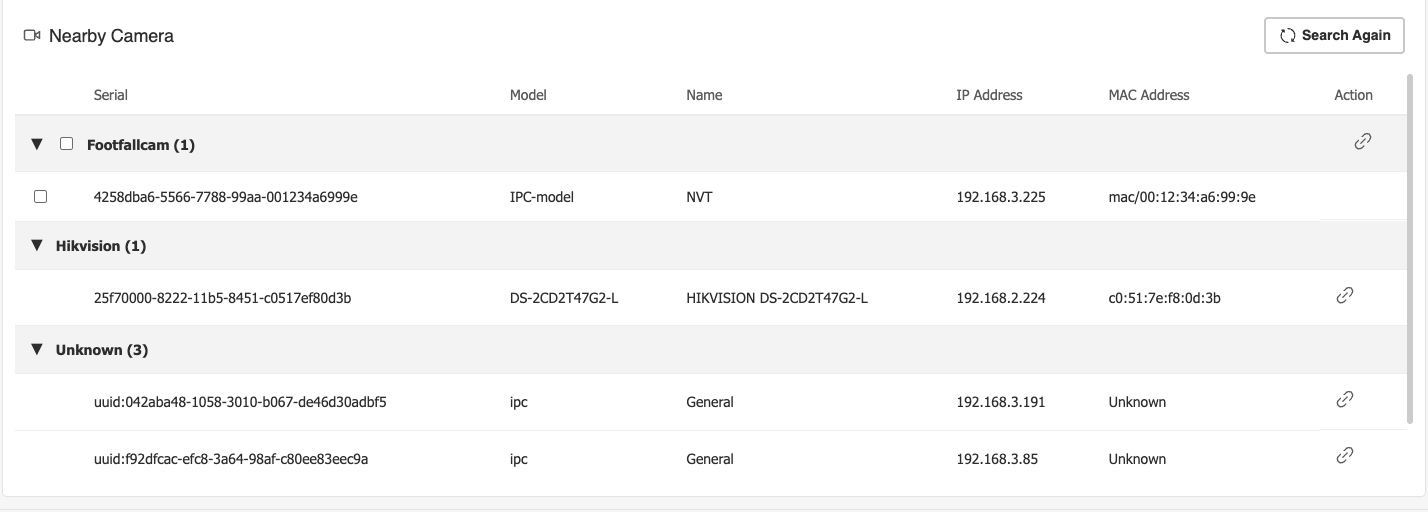
You will see a list of nearby compatible devices and the list will be grouped by the device brand. Users can click on the Search Again button on the top right of the nearby cameras list to search again.
-
Based on the brand, the binding workflow will differ.
-
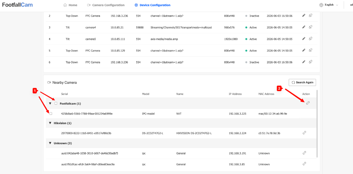
FootfallCam: Users can select multiple FootfallCam devices by clicking on the checkboxes and then they can click on the Bind button on the FootfallCam brand header to bind all selected cameras.
-
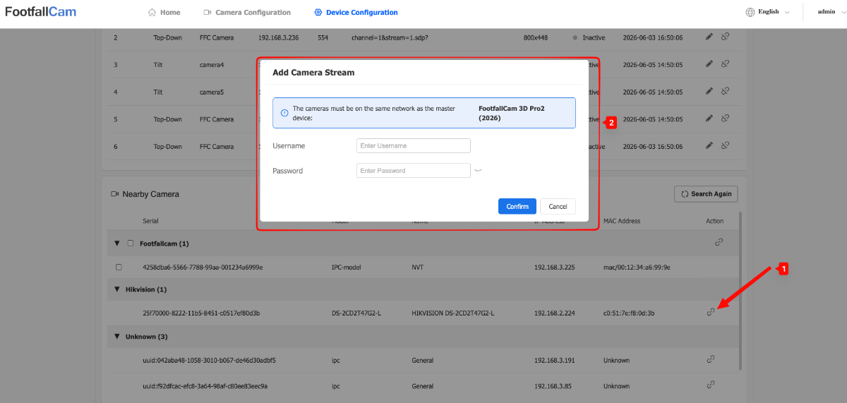
Known Brands: Users can click on the Bind button to bind the selected camera. Users will be prompted to enter username and password in order to bind the camera.
-
Unknown Brands: Users can click on the Bind button to bind the selected camera. Users will then be directed to the Add Camera popup in which they must fill the popup similarly to Method 2 below.
-
Note: This method is currently not supported by Centroid devices yet.
Method 2: Manually Add Camera
-
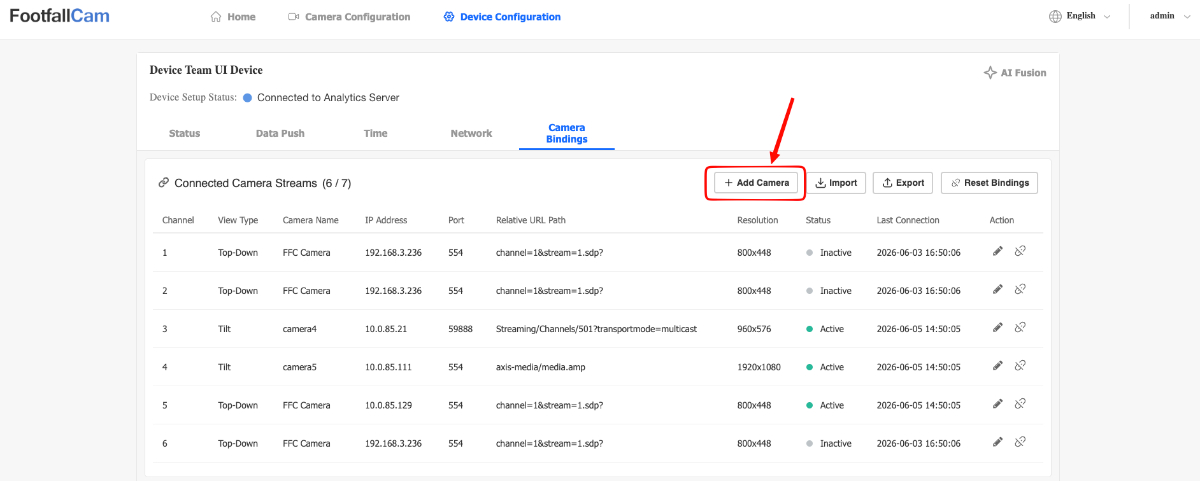
In the Camera Bindings section, click on the Add Camera button. A popup should appear to fill in the camera stream details.
-
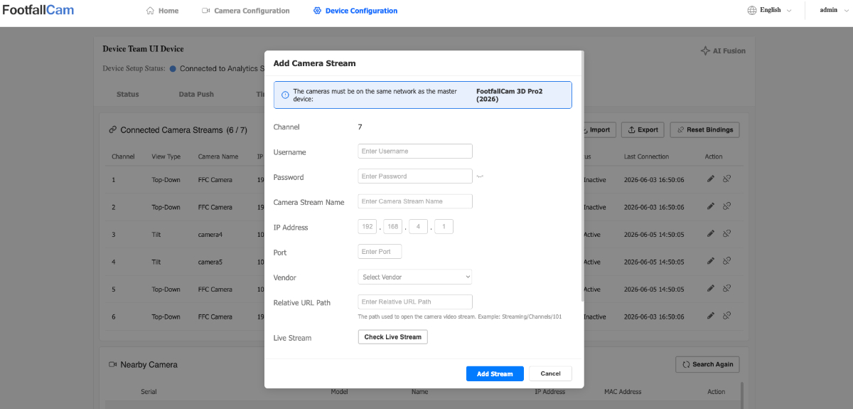
Please fill up all details in the popup, ensure that you also scroll down as there is a required view type field as well.
-
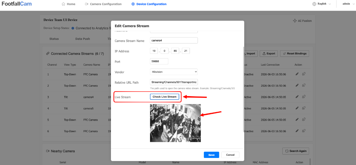
Users can click on the Check Live Stream button to preview a snapshot of the stream to verify that the camera details are correct.
-
Click on the Add Stream button to add the camera stream.
Note:
-
Top-Down View is the default view type that accounts for the downward-facing perspective of ceiling-mounted devices, ensuring accurate field-of-view coverage.
-
Tilt View is the view type that accounts for the angled mounting perspective of CCTV devices, ensuring accurate field-of-view coverage.
-
The selected view type will impact the available models that can be selected for the camera stream.
Editing Camera Stream
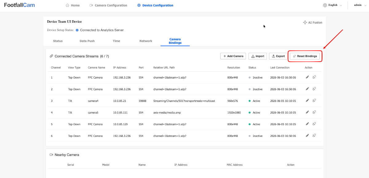
Users can edit a camera stream by clicking on the Edit Action button as shown below. A similar popup as the Add Camera Stream popup will appear.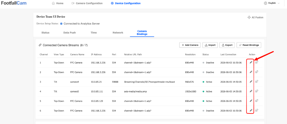
Importing / Exporting Camera Streams
-
Users can import and export their current camera bindings by clicking on the Import / Export button.
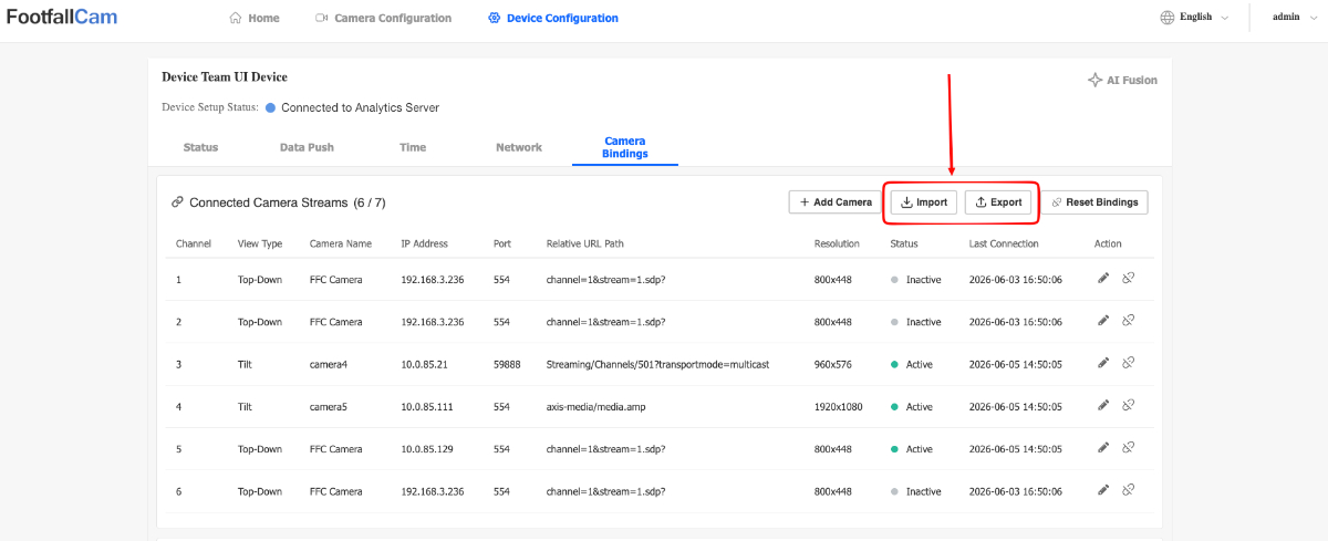
-
The buttons will open a dropdown in which the user can select to import or export bindings.
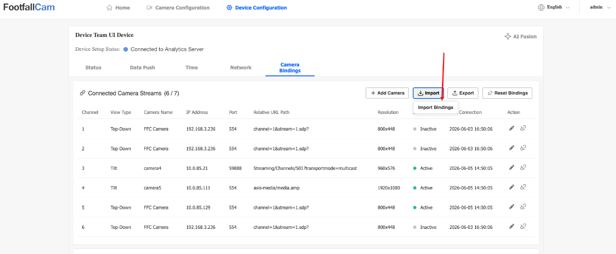
-
When Import Bindings is selected, the user will be prompted to select a file to be imported.
Note: The selected file must be a .csv file and has the following format:
-
When Export Bindings is selected, a .csv file will be downloaded to the user's device.
Unbinding Camera Streams
Users can unbind your camera streams in one of two ways:
-
Unbind a Specific Stream: Disconnect an individual camera stream while leaving others active.
-
Unbind All Streams: Disconnect all connected camera streams simultaneously.
-
Users can click on the unbind icon to unbind the specific camera stream.
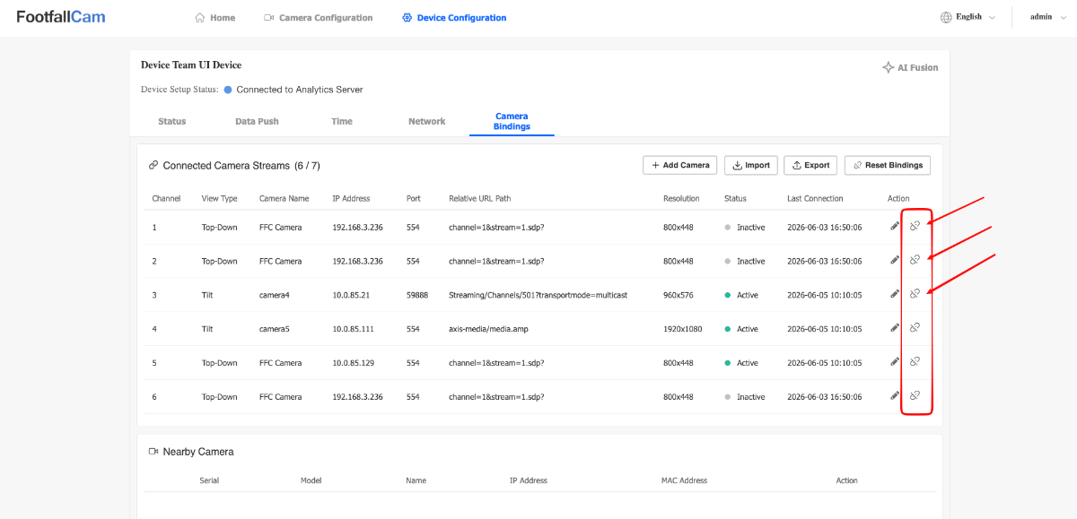
-
The user will be prompted with a confirmation prompt before they can unbind. Click Confirm to unbind the camera stream.
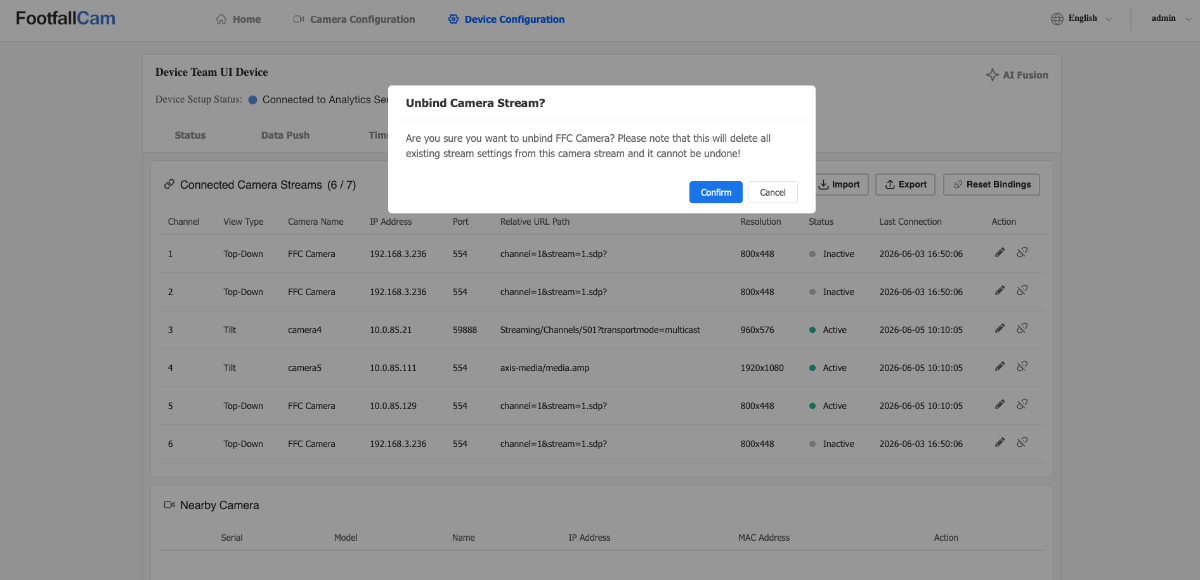
Note: The user can also unbind all cameras if needed by clicking on the Reset Bindings button.
3.6.9 Site Network Requirements for using FootfallCam Pro2
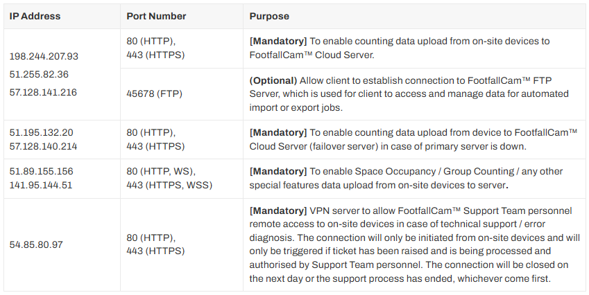
3.6.9.1 Firewall Whitelisting Requirements
- To ensure uninterrupted communication between FootfallCam devices and FootfallCam Cloud services, please ensure the following IP addresses and ports are whitelisted in the site's network firewall, proxy, and VPN security rules.
3.6.9.2 Proxy Server Considerations
- If the site network enforces internet access through a proxy server, please configure the Proxy Settings on the Pro2 device control panel accordingly, see an example below:
- If the proxy uses SSL inspection, the network administrator may need to whitelist the FootfallCam's cloud domain to prevent TLS handshake errors.
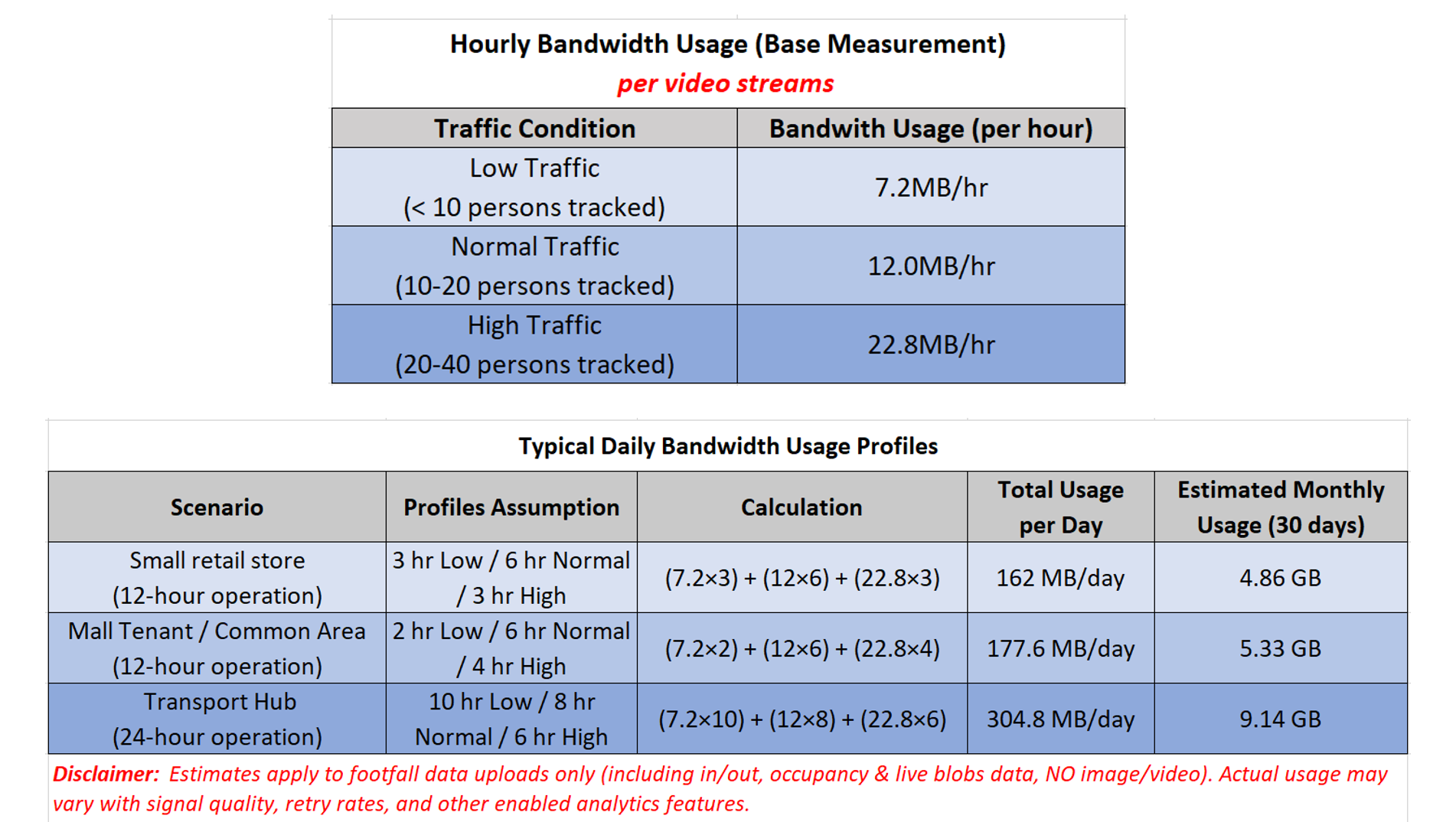
3.6.9.3 Bandwidth Usage Estimation
Entrance Counting ONLY
- 2MB/day (12hr operation), assume hourly 100 people In&Out footfall activities.
Path Map Playback Enabled
- On average 60MB/day (12hr operation), assume 20 people being tracked actively in the liveview.
- Can opt for out of operating hour data uploading
Live-blobs Viewing Enabled: