Introduction
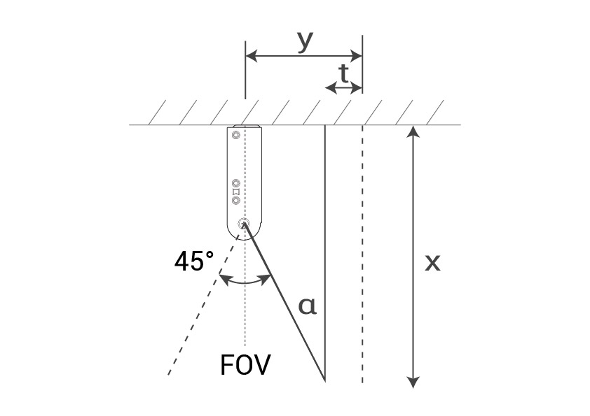
FootfallCam 3D Mini™ have a different coverage on Front View (91°) and Side View (45°). It required different calculation in order to ensure there is no obstacle blocking the view. Figure 1 illustrates the dual perspectives of the FootfallCam 3D Mini™, showcasing the Front View at 91° and the Side View at 45°.
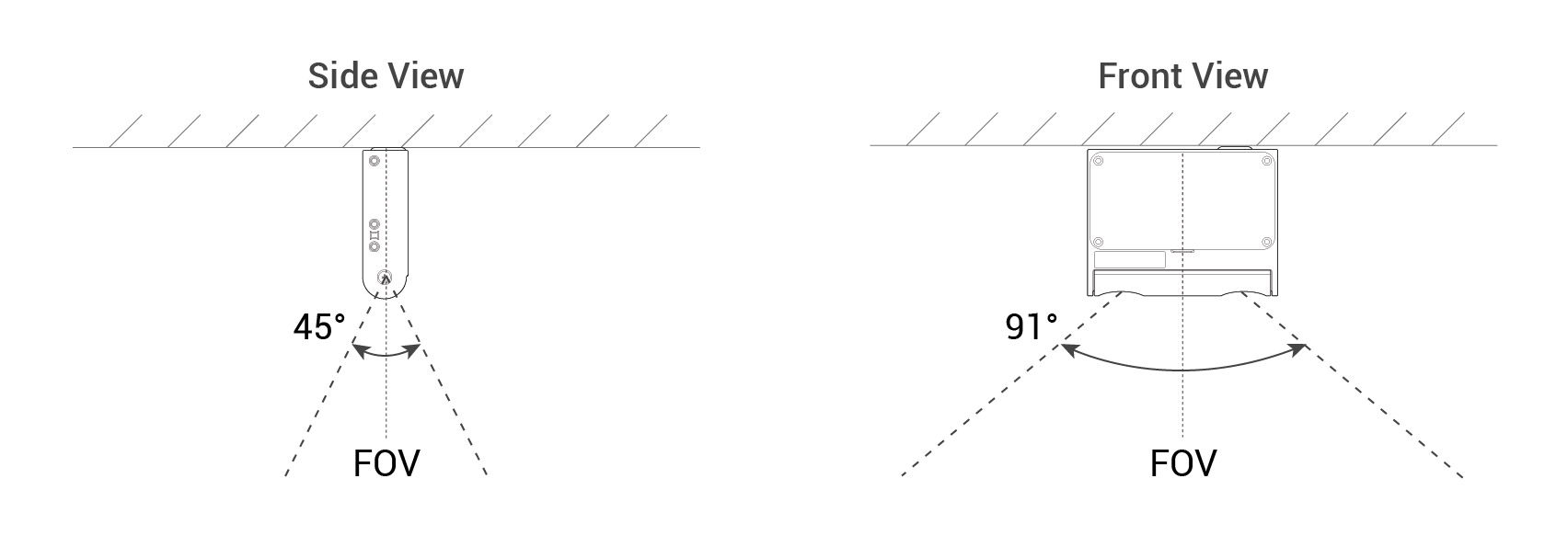 Figure 1: Side View and Front View of FootfallCam 3D Mini™
1.0 Understanding Clearance Distances: Visual Overview
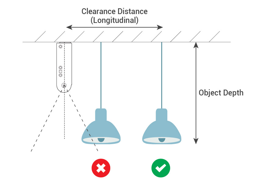
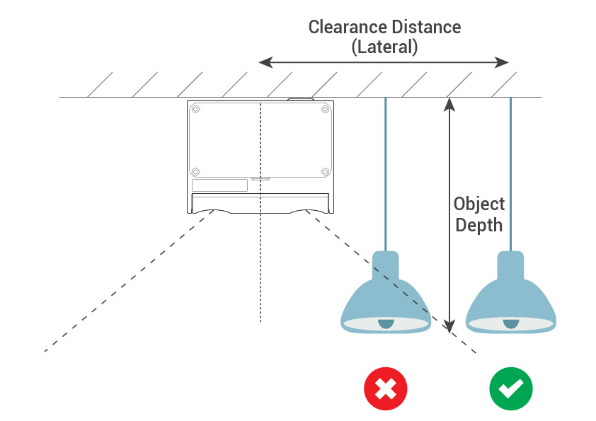
This section provides a visual presentation of added obstacles at recommended distances for both Longitudinal and Lateral perspectives, as shown in Figure 2. For detailed calculations, refer to Section 2.0 Formula.
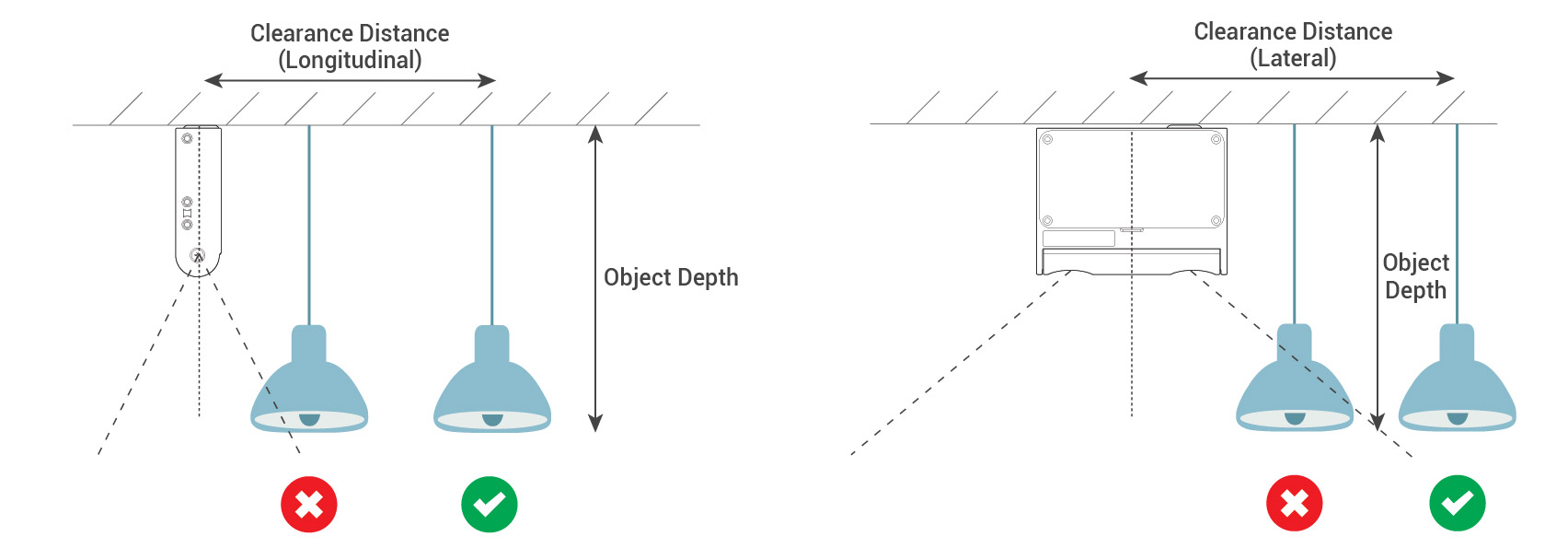 Figure 2: Obstacle Placement Overview
*Add tolerance to allow some error in location of installation*
2.0 Clearance Distance Formulas
This formula is applicable to both flat surface mounting with a drop-down obstacle and slanted surface mounting, providing a comprehensive solution for calculating clearance distance in various scenarios.
Figure 3 demonstrates the calculation for clearance distance, simplifying the understanding of this crucial measurement.
|
y = t + xtan α
|
Figure 3 |
2.1 Flat Surface Mounting for Drop-Down Obstacle
Calculate the min. clearance distance required between FootfallCam 3D Mini V3™ and the drop down obstacle (e.g. decorations, exit signage, bulk head, wall. etc.) to prevent the counter live view being blocked and not able to count accurately.
2.2 Slanted surface mounting
Calculate the precise angle required for slanted surface mounting using the same formula. Ensuring accurate placement for the FootfallCam 3D Mini™ and enhancing the counter's live view for precise counting.
Figure 4: Illustrates the FootfallCam 3D Mini™ positioned on a slanted surface, highlighting optimal angle placement for enhanced live view accuracy.
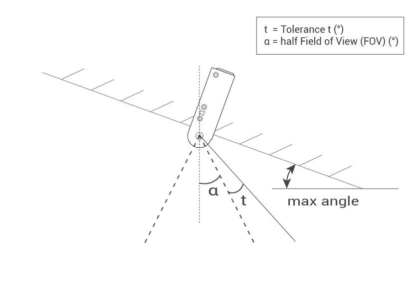 Figure 4: Optimal Slanted Surface Mounting
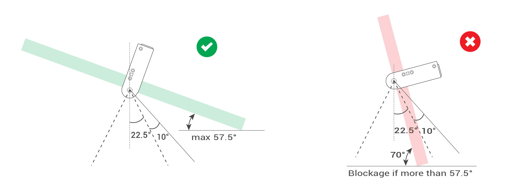 Figure 5: Optimal vs. Exceeded Angle Comparison
*Add tolerance to allow some error in angle measurement*
Conditions applied:
| tolerance t (°) | 10 |
| half Field of View (FOV) α (°) | 22.5 |
| max angle (°) | 57.5 |

